
Antenna device

a technology of antenna array and antenna earthing, which is applied in the direction of individual energised antenna array, independent non-interaction antenna combination, antenna earthing, etc., can solve the problem of difficult to reduce and achieve the effect of reducing the size of the antenna

Active Publication Date: 2021-03-30
MURATA MFG CO LTD
View PDF30 Cites 0 Cited by
  • Summary
  • Abstract
  • Description
  • Claims
  • Application Information

AI Technical Summary

Benefits of technology

[0013]Since a part of the second ground conductor operates as a part of the parasitic element of the second antenna, the feed element of the second antenna may be disposed near the second ground conductor operating as the ground electrode of the first antenna. In addition, it is not necessary to dispose the parasitic element separately. Therefore, reduction in the size of the antenna may be achieved.
[0019]When the operating frequency of the second antenna falls within a range from 1 GHz to 6 GHz, it is easy to finely adjust the resonant frequency by using the impedance element.
[0021]The second ground conductor is provided in or on the module substrate, and the feed element of the second antenna is supported by the module substrate. Thus, the feed element is disposed near the second ground conductor, facilitating reduction in the size.
[0022]Since the second ground conductor operates as a part of the parasitic element of the second antenna, the feed element of the second antenna may be disposed near the second ground conductor operating as the ground electrode of the first antenna. In addition, it is not necessary to dispose the parasitic element separately. Therefore, reduction in the size of the antenna may be achieved.

Problems solved by technology

Therefore, it is difficult to reduce the antenna in size.

Method used


Image

  • Antenna device
  • Antenna device
  • Antenna device

Examples


first embodiment

[0032]FIG. 1 illustrates a schematic side view of an antenna device according to a First ground conductors 11 and wiring patterns 12 are disposed inside of and on a surface of a main substrate 10. FIG. 1 illustrates a first ground conductor 11 and a wiring pattern 12 which are disposed on the surface. An electronic circuit element 13 is mounted above the main substrate 10.

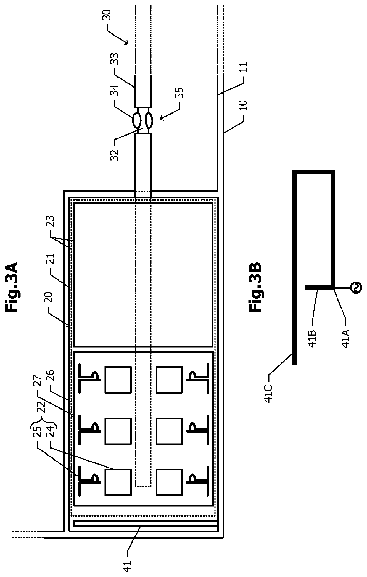
[0033]An antenna module 20 includes a module substrate 21, a first antenna 22, and a second ground conductor 23. The first antenna 22 includes, for example, multiple radiating elements supported by the module substrate 21, and operates as an adaptive array antenna. As the multiple radiating elements, for example, patch antennas, printed dipole antennas, and the like are used. The antenna module 20 also includes a diplexer, a high-frequency receiving circuit, a phase shifter, a low noise amplifier, and a power amplifier. The second ground conductor 23 operates as the ground electrode for the first antenna 22.

[0034]...

second embodiment

[0073]In contrast, in the second embodiment, the resonant frequency of the parasitic element 42 may be finely adjusted by adjusting the impedance of the impedance element 37. In the case where the operating frequency of the second antenna 40 is low, even when the impedance value of the impedance element 37 is changed, the change of the resonant frequency is small. In the case where the operating frequency of the second antenna 40 falls within a range between 1 GHz and 6 GHz inclusive, a method of adjusting the resonant frequency by using the impedance element 37 is especially effective.

[0074]The embodiments are exemplary. Needless to say, partial replacement or combination of configurations according to the different embodiments may be made. Similar effects caused by similar configurations according to multiple embodiments are not particularly described. In addition, the present disclosure is not limited to the above-described embodiments. For example, the fact that various changes,...


PUM


Abstract

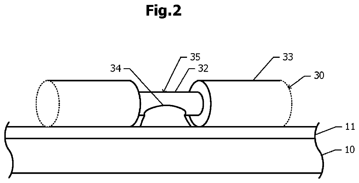
A first ground conductor is disposed in or on a main substrate. In or on an antenna module, a first antenna and a second ground conductor operating as a ground electrode of the first antenna are disposed. A coaxial cable including a core wire and an outer conductor feeds power to the first antenna. The outer conductor is electrically connected to the first ground conductor at a first position, and is connected to the second ground conductor at a second position. A second antenna including a feed element and a parasitic element operates at a lower frequency than the operating frequency of the first antenna. The second ground conductor and a part of the outer conductor from the first position to the second position also serve as the parasitic element of the second antenna.

Description

[0001]This is a continuation of International Application No. PCT / JP2016 / 076334 filed on Sep. 7, 2016 which claims priority from Japanese Patent Application No. 2015-202531 filed on Oct. 14, 2015. The contents of these applications are incorporated herein by reference in their entireties.BACKGROUNDTechnical Field[0002]The present disclosure relates to an antenna device including a feed element and a parasitic element.[0003]In Patent Document 1 described below, a wideband antenna operating in the GHz band is disclosed. The wideband antenna includes a planar antenna element, a planar parasitic element, and a ground plate which are disposed on a surface of a substrate. The planar antenna element is disposed so as to be spaced apart from the ground plate in the in-plane direction. The planar parasitic element extends from the ground plate, and is disposed so as to be opposite the planar antenna element in the in-plane direction. The core wire of a coaxial cable is connected to the plana...

Claims


Application Information

Patent Timeline
Patent Type & Authority Patents(United States)
IPC IPC(8): H01Q21/28H01Q1/48H01Q1/46H01Q5/378H01Q5/35H01Q1/22H01Q1/38H01Q19/00H01Q21/06
CPCH01Q1/48H01Q1/2291H01Q1/38H01Q1/46H01Q5/35H01Q5/378H01Q19/005H01Q21/28H01Q21/062H01Q21/065
Inventor IZAWA, MASAHIRO
Owner MURATA MFG CO LTD
Learn More