
Projector

a projector and projection device technology, applied in the field of projectors, can solve problems such as irregular luminance and no other way, and achieve the effect of reducing or preventing inhomogeneity in brightness

Inactive Publication Date: 2007-01-30
SEIKO EPSON CORP
View PDF3 Cites 2 Cited by
  • Summary
  • Abstract
  • Description
  • Claims
  • Application Information

AI Technical Summary

Benefits of technology

[0007]Exemplary aspects of the invention, therefore, provide a projector that can be readily fine-adjusted after assembly and hardly causes deterioration of an image resulted from stray light.
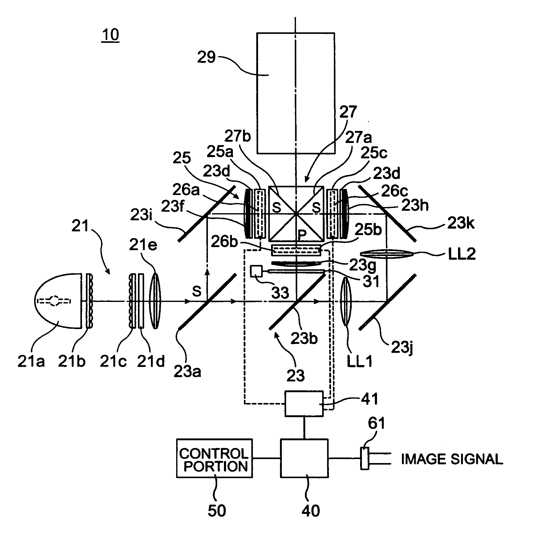
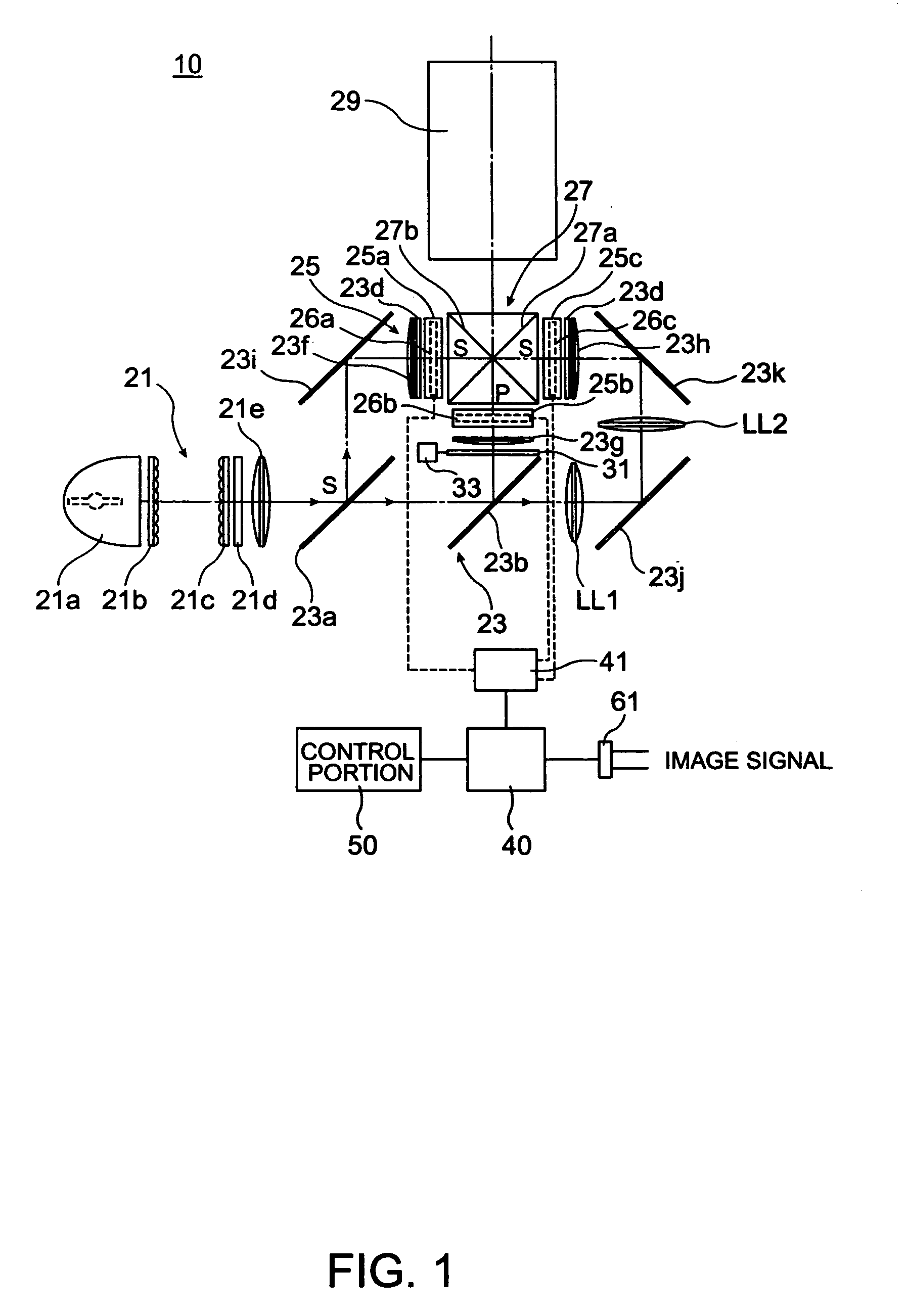
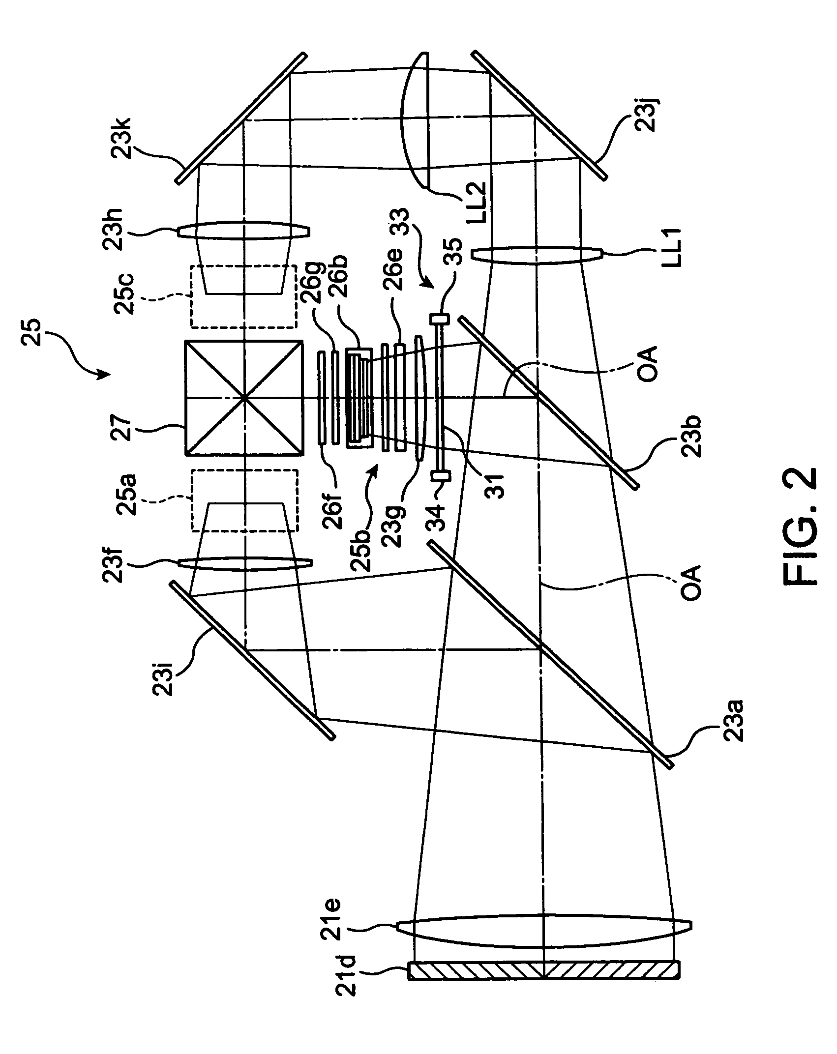
[0018]According to an exemplary aspect of the invention, field lenses, respectively placed in preceding stages of the light modulating devices of respective colors, to regulate an angle of incidence of the illumination light on each of the light modulating devices are further provided. The neutral density filter is placed in a preceding stage of at least one of the field lenses. In this case, even in a case where converged light or the like is generated unexpectedly due to return light via the field lens or the like, such converged light can be guided to the outside of the light path. Hence, not only can the brightness of a projection image be made homogeneous in all the portions, but also the occurrence of irregularities in color and inhomogeneity in brightness can be reduced or prevented.

Problems solved by technology

With the projector as described above, however, in a case where one wishes to fine-adjust the transmittance of the neutral density filter after assembly, there is no other way but to replace the neutral density filter or the like.
In this case, however, reflection light may generate stray light, which gives rise to irregularities in luminance.

Method used


Image

  • Projector
  • Projector
  • Projector

Examples


first exemplary embodiment

[0028

[0029]The structure of a projector according a first exemplary embodiment of the invention will now be described with reference to the drawings.

[0030]FIG. 1 is a schematic showing an optical system of the projector of the first exemplary embodiment. The projector 10 includes: a light source device 21 to generate light-exemplary light; a light division optical system 23 to split light-source light from the light source device 21 into beams of light for three colors of RGB; a light modulation portion 25 illuminated by beams of illumination light of respective colors emitted from the light division optical system 23; a cross dichroic prism 27 to synthesize images of light of respective colors from the light modulation portion 25; and a projection lens 29 serving as a projection optical system to project images of light synthesized in the cross dichroic prism 27 onto a screen (not shown). Further, the projector 10 includes an image processing portion 40 to generate driving signals ...

second exemplary embodiment

[0054

[0055]A projector according to a second exemplary embodiment is a projector employing a digital mirror device (DMD) including a light-modulating element of a reflective type.

[0056]FIG. 9 is a schematic showing the optical system of the projector of the second exemplary embodiment. The projector 210 includes a light source device 221, a color wheel 271, a neutral density filter 231, a digital mirror device (DMD) 225, and a projection lens 229, which are placed sequentially along a system optical axis SA.

[0057]The light source device 221 includes a light source lamp and a reflector. Light-source light from the light source device 221 goes incident on the color wheel 271 and is split into beams of illumination light of respective colors that switch with time by passing through the color wheel 271, which go incident on the digital mirror device 225 by way of the neutral density filter 231. The digital mirror device 225 is a spatial light-modulating device of a reflection direction ...


PUM


Abstract

To provide a projector that hardly causes deterioration of an image resulted from stray light. A neutral density filter, of which posture can be fine-adjusted by a posture regulating mechanism, is placed in a space between a second dichroic mirror and a liquid crystal light valve. Thus, it is possible to remove stray light, corresponding to condensed light resulted from multi-pass through a field lens or the like, to the outside of a light path by merely tilting the neutral density filter adequately. It is thus possible to project an image having homogeneous brightness (illuminance at the white level) across the entire screen, which in turn makes it possible to project an image having no irregularities in color across the entire screen.

Description

BACKGROUND OF THE INVENTION[0001]1. Field of Invention[0002]Exemplary aspects of the present invention relate to a projector that projects an image with the use of a liquid crystal panel or any other display apparatus.[0003]2. Description of Related Art[0004]A related art projector achieves desired white balance, for example, by decreasing a quantity of green light through the use of a neutral density filter placed on a light path for green light to absorb or reflect green light (See JP-A-10-311968.SUMMARY OF THE INVENTION[0005]With the projector as described above, however, in a case where one wishes to fine-adjust the transmittance of the neutral density filter after assembly, there is no other way but to replace the neutral density filter or the like.[0006]It is possible to replace the neutral density filter with a neutral density filter of a reflective type. In this case, however, reflection light may generate stray light, which gives rise to irregularities in luminance.[0007]Ex...

Claims


Application Information

Patent Timeline
Patent Type & Authority Patents(United States)
IPC IPC(8): G03B21/14G03B21/26G03B21/20G03B21/00H04N5/74H04N9/31
CPCG03B21/14H04N9/3197H04N9/315G03B21/208G03B21/00G03B21/20
Inventor YOSHIDA, KANJIKARASAWA, JOJI
Owner SEIKO EPSON CORP
Learn More