Digital holographic microscopy

a holographic microscopy and digital technology, applied in the field of digital holographic microscopy, can solve the problems of distorted reconstruction, complex interference pattern of spaced fringes, complicated reconstruction algorithm, etc., and achieve the effect of reducing the number of optical elements

Active Publication Date: 2011-02-24
NANYANG TECH UNIV +1
View PDF6 Cites 6 Cited by
  • Summary
  • Abstract
  • Description
  • Claims
  • Application Information

AI Technical Summary

Benefits of technology

[0025]As will be apparent from the following description, preferred embodiments of the present invention allow digital off-axis holograms to be obtained using a cube beam splitter that both splits and combines a diverging spherical wavefront emerging from a microscope objective. With this arrangement, the phase curvature introduced by the microscope objective together with the illuminating wave to the object wave can be physically compensated when a plane numerical reference wavefront is used for the reconstruction of the recorded digital hologram. The features of the preferred embodiments of the present invention allow an implementation of digital holographic microscopy benefiting from simplicity, minimal number of optical elements, and insensitivity to vibration. These and other related advantages will be readily apparent to skilled persons from the description below.

Problems solved by technology

The reference wave and object wave are then arranged to interfere with one another, thus producing a complex interference pattern of spaced fringes.
Since the phase curvature is not present in the reference wave, interference of the object wave and reference wave will produce a hologram that results in a distorted reconstruction.
Both approaches are done numerically, which complicates the reconstruction algorithm and makes numerical reconstruction a time-consuming process.

Method used


Image

  • Digital holographic microscopy
  • Digital holographic microscopy
  • Digital holographic microscopy

Examples


Embodiment Construction

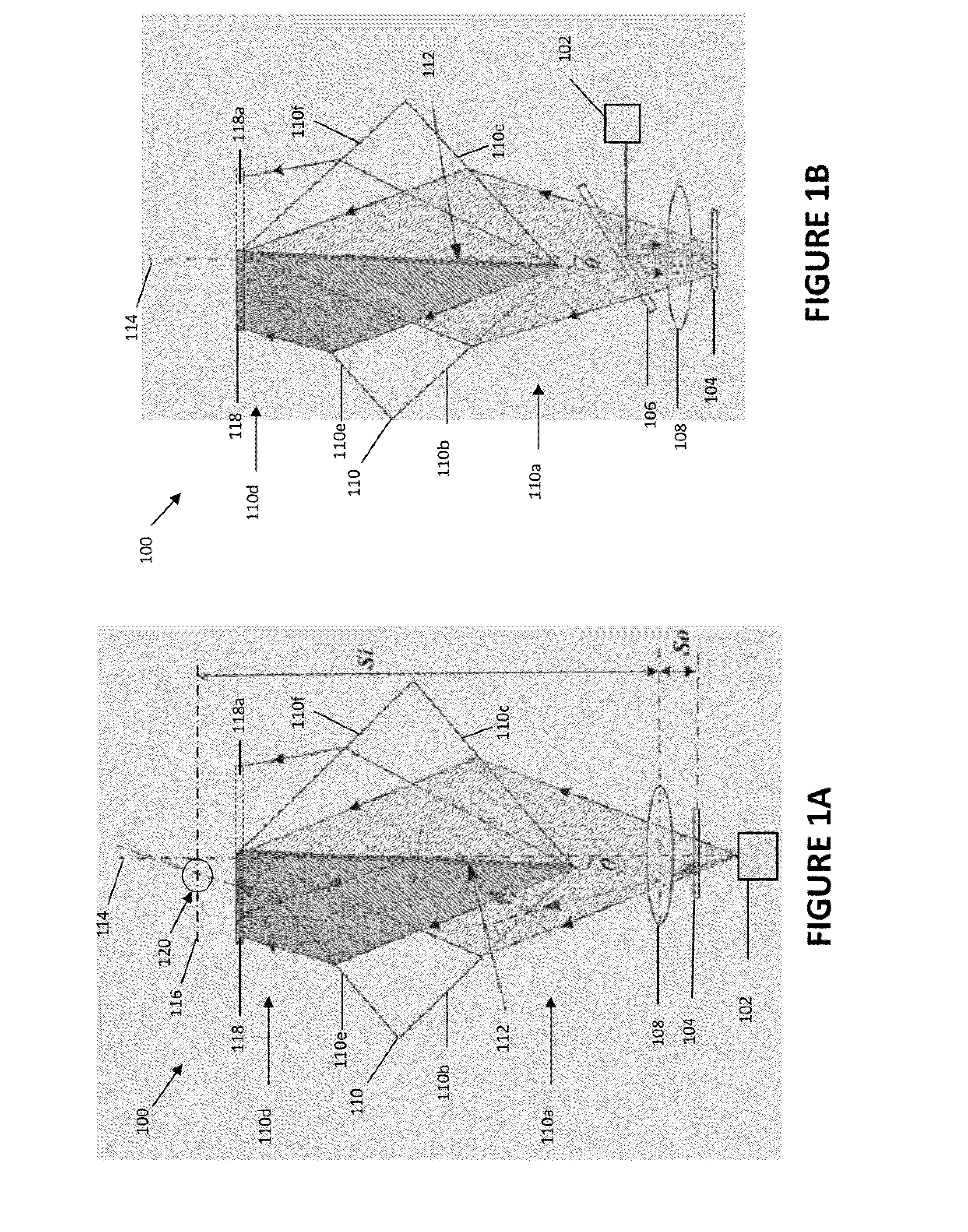
[0036]Referring to FIGS. 1A and 1B, preferred embodiments of the digital holographic microscope are shown generally as 100. The digital holographic microscope 100 in FIG. 1A is arranged in a transmission mode (where light from a source 102 is transmitted through the object of interest 104), while the digital holographic microscope 100 in FIG. 1B is arranged in a reflection mode (where light from the source 102 is reflected by a beam splitter 106 to the object of interest 104).

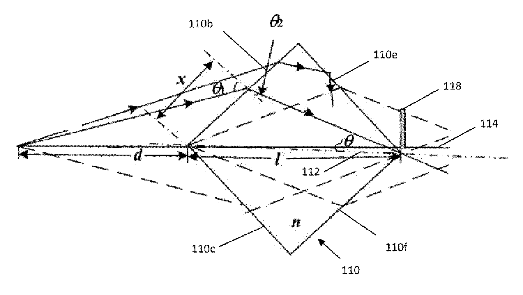
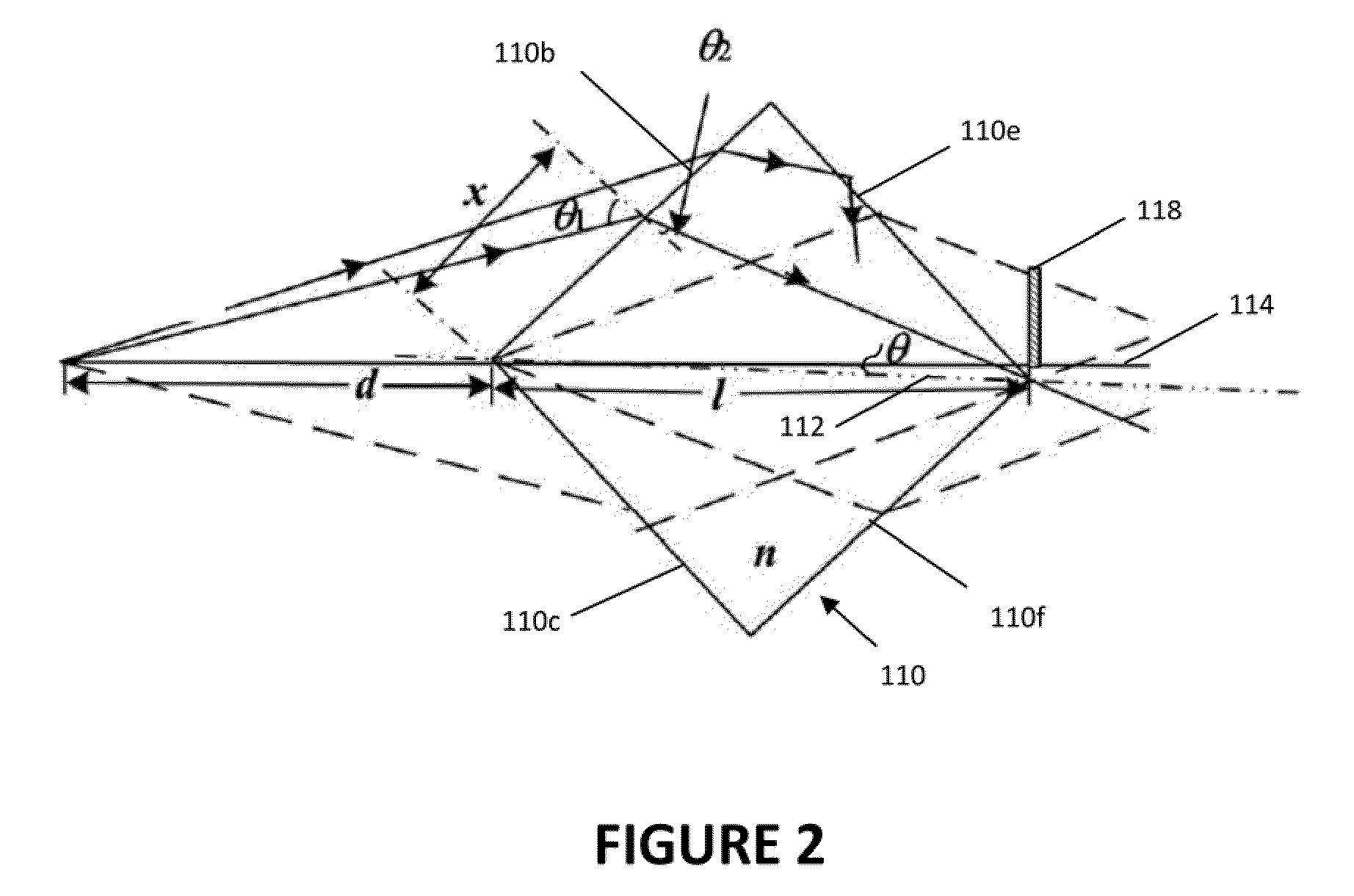
[0037]Each digital holographic microscope 100 includes a microscope objective 108 and a beam splitter 110. In the preferred form, the beam splitter 110 is a single cube beam splitter that includes a central semi-reflective layer 112 within outer walls of the cube beam splitter 110. The microscope objective 108 is centred about an optical axis 114, while the semi-reflective layer 112 of the cube beam splitter 110 forms a small non-zero angle θ with the optical axis 114. The angle θ is preferably in the range of ...


PUM


Abstract

An optical configuration for a digital holographic microscope and a method for digital holographic microscopy are presented. In one embodiment, digital off-axis holograms are obtained using a cube beam splitter (110) to both split and combine a diverging spherical wavefront emerging from a microscope objective (108). When a plane numerical reference wavefront is used for the reconstruction of the recorded digital hologram, the phase curvature introduced by the microscope objective (108) together with the illuminating wave to the object wave can be physically compensated.

Description

FIELD OF THE INVENTION[0001]The present invention relates generally to digital holographic microscopy, and more particularly, but not exclusively, to digital holographic microscopy with physical phase compensation.BACKGROUND TO THE INVENTION[0002]Image recording of a specimen is most commonly carried out based on a recording of the intensity of light received from the specimen. However, since the interaction of light with a specimen modifies both the light intensity and phase, image recording can also be carried out based on phase detection.[0003]Holography provides a means by which both phase and intensity information can be determined from a single record called a hologram. To obtain a hologram using conventional techniques, a source beam is first split by a beam splitter into a first part, and a second part that is sent to the specimen. The first part is commonly referred to as a reference wave while light from the second part that is scattered from the specimen is referred to as...

Claims


Application Information

Patent Timeline
Patent Type & Authority Applications(United States)
IPC IPC(8): G03H1/00
CPCG03H1/0402G03H1/0443G03H1/0866G03H2001/005G03H2001/045G03H1/041G03H2001/0469G03H2001/0471G03H2222/50G03H2223/18G03H2001/0456G03H2001/0452
Inventor ASUNDI, ANAND KRISHNAQU, WEIJUANCHOO, OI
Owner NANYANG TECH UNIV
Why Eureka
Try Eureka