
Solenoid-actuated diaphragm valve

a diaphragm valve, solenoid technology, applied in the direction of valve details, valve arrangement, valve operating means/releasing devices, etc., can solve the problems of unbalanced fluid pressure above the diaphragm, pressure on the diaphragm against the valve seat, and diaphragms that are detached, etc., to achieve high fluid pressure, promote fluid flow, and relieve pressure

Inactive Publication Date: 2011-02-24
KOZAK EUGENIUSZ
View PDF14 Cites 9 Cited by
  • Summary
  • Abstract
  • Description
  • Claims
  • Application Information

AI Technical Summary

Benefits of technology

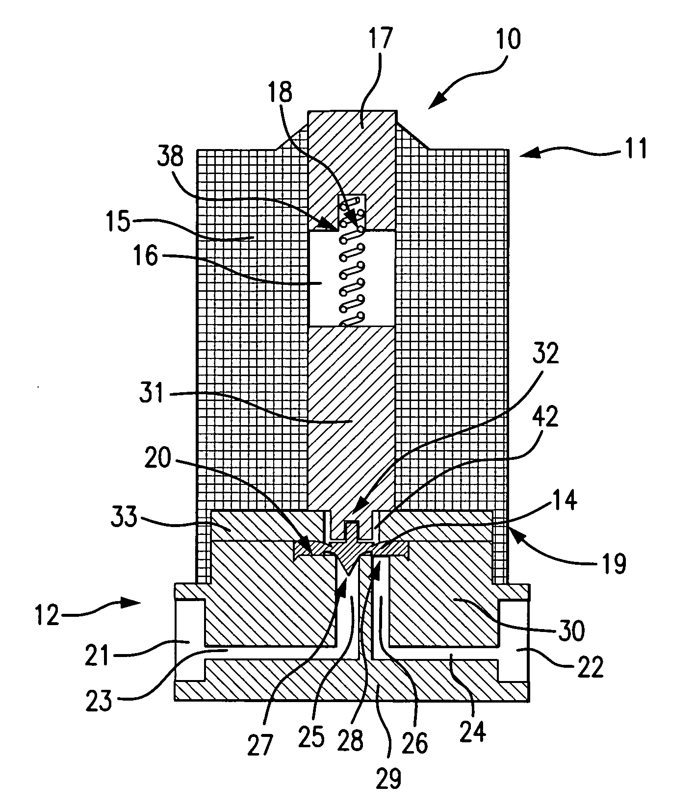
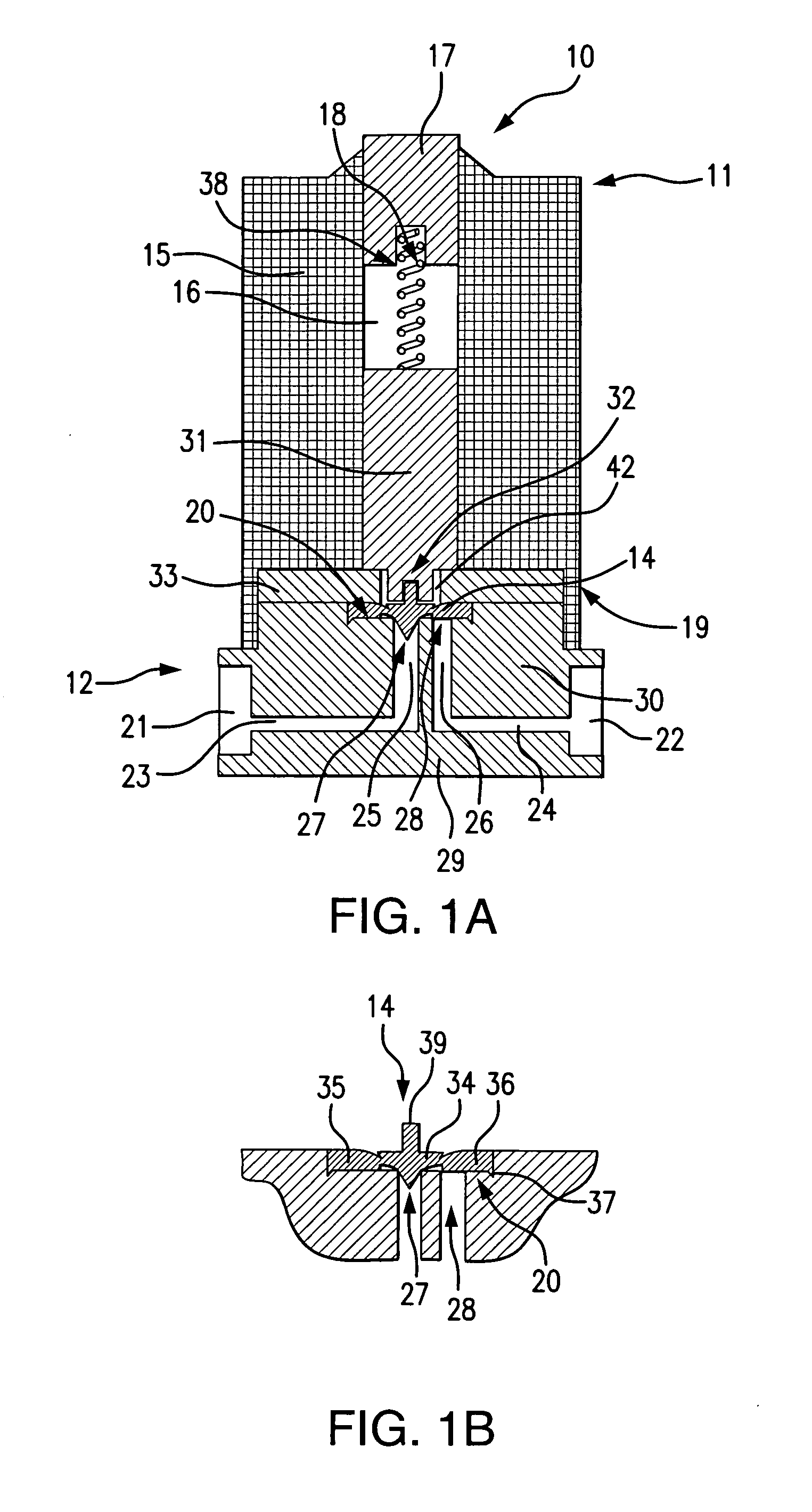
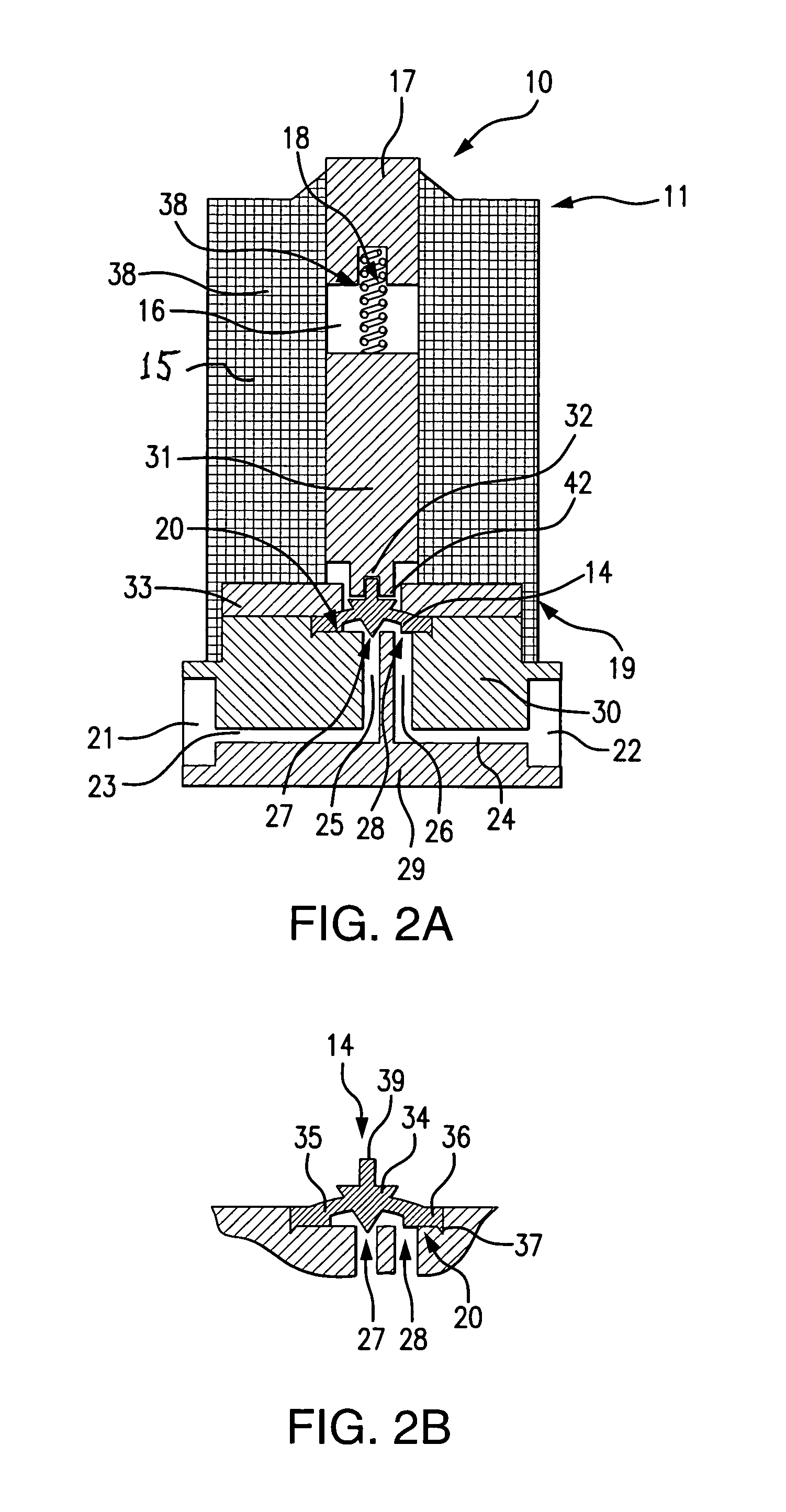
[0031]An object of the present invention is to provide a solenoid-actuated diaphragm valve that minimizes the “dead volume” of fluid that is retained inside the valve when it is in the closed position, thereby reducing the potential for contamination of the fluid and / or corrosion of the valve components.
[0032]Another object of the present invention is to provide a solenoid-actuated diaphragm valve that limits the degree of deformation of the diaphragm as it flexes between the engaged and disengaged positions, thereby reducing fatigue of the elastomeric material which can cause diaphragm failure over time.
[0033]A further object of the present invention is to provide a solenoid-actuated diaphragm valve that operates with a short plunger stroke, that is, a short distance through which the plunger must be withdrawn upward through the plunger guide to effect the disengagement of the diaphragm from the valve seat, thereby consuming less electrical energy, enabling quicker valve response time, and reducing component wear.
[0036]Still another object of the present invention is to provide a solenoid-actuated diaphragm valve in which the resilient “ring” area of the diaphragm flexes upward in the energized state (open position), so that the expanded area under the upwardly flexed ring relieves pressure and promotes even fluid flow, rather than creating a dead volume, as would be the case if the ring flexed upward in the closed position.
[0039]1. A “double seal” diaphragm that seals both the central valve seat inlet and the peripheral valve seat outlet in the closed position and leaves virtually no dead volume. The diaphragm has a post-like poppet stem at the center of its reverse side, by means of which the diaphragm is attached to a recess in the proximal end of the plunger shaft. This “attached diaphragm” design allows the diaphragm to move in secure alignment with the plunger while at the same time having a shape unconstrained by the plunger structure.

Problems solved by technology

In Allen, U.S. Pat. No. 4,295,631, the de-energized plunger does not push the diaphragm, but instead closes a pilot valve extending through the center of the diaphragm, thereby creating an unbalanced fluid pressure above the diaphragm which urges it against the valve seat.
There are a host of problems associated with both the “integral diaphragm” and “detached diaphragm” designs.
While Gilchrist avoids these problems, it does so at the cost of a quite constricted fluid passage through the valve seat in the open position, which will retard the fluid flow and create pressure build-up on the diaphragm.
As for the detached diaphragm designs, Allen and Sule achieve a short plunger stroke but involve considerable dead volume.
While Holtermann and Kazama achieve both a short plunger stroke and minimal dead volume, they rely critically on the alignment of the plunger with the center of the diaphragm, which is likely to deviate over time.
Moreover, repeated impact on the plunger on the center of the diaphragm will produce scoring and accelerate fatigue failure over time.
Both Holtermann and Kazama have the additional drawback of employing diaphragms having a uniform cross-sectional area.
Because such diaphragms must retain resiliency across their entire cross section, they cannot be thickened to withstand high pressure and are prone to failure when fluid pressure exceeds certain limits.
This is inefficient, since the diaphragm cross-section should be thinnest in the area where most of the deformation occurs.
As can be seen in FIG. 6, however, the combination of this blunt central projection and the pronounced upward flexing of the medial ring area leaves a considerable dead volume when the valve is closed.
If we consider the prior art designs in which the diaphragm seals only the central valve seat inlet / outlet, we find that these designs all have a relatively high dead volume, due to the area left unsealed between the diaphragm and the peripheral valve seat outlet / inlet.
On the other hand, prior art designs featuring “double seal” diaphragms, which cover both the valve seat inlet and outlet, tend to have minimal dead volume.
This has the disadvantage of leaving the diaphragm free to flex vertically across the entire width of the valve seat.

Method used


Image

  • Solenoid-actuated diaphragm valve
  • Solenoid-actuated diaphragm valve
  • Solenoid-actuated diaphragm valve

Examples


Embodiment Construction

[0049]In the following detailed description of the preferred embodiment, it should be understood that the novel features of the present invention relate to the plunger, the constraining plate and the diaphragm, and that the other features described herein are merely typical features of a generic solenoid-actuated diaphragm valve. Therefore, the configuration of the various elements of the valve other than the plunger, the constraining plate and the diaphragm are for illustrative and exemplary purposes only, and are not intended to limit the scope of the present invention. Thus, for example, while a specific configuration of the valve body and valve seat is described herein, this configuration can be varied to according to the desired flow pattern of the valve without impairing the utility or applicability of the present invention.

[0050]As used in the following description, the term “proximal” refers to the part of an element oriented toward the base of the valve, while the term “dis...


PUM


Abstract

A solenoid-actuated diaphragm valve achieves minimal dead volume, tolerance of high pressures, prolonged diaphragm life, and energy conservation using a three-sector diaphragm in concert with a constraining plate which confines vertical displacement to the central sectors of the diaphragm.

Description

REFERENCE TO RELATED APPLICATION[0001]This application is a continuation-in-part of application Ser. No. 12 / 071,829 filed Feb. 27, 2008.FIELD OF THE INVENTION[0002]The present invention relates to valves that control fluid flow by using a flexible diaphragm to seal one or more fluid passages, and more particularly to valves in which the sealing diaphragm is deformed through the application of a biasing force transmitted by the movement of a solenoid armature.BACKGROUND OF THE INVENTION[0003]Solenoid-actuated diaphragm valves are widely used in fluid distribution systems to control fluid flow. In isolation valves, the fluid can be isolated and channeled to designated passages and / or chambers within the valve through the displacement of a flexible diaphragm. The displacement of the diaphragm typically causes it to engage or disengage with a valve seat where two or more fluid passages terminate. Typically, in the neutral or de-energized condition, the diaphragm engages the valve seat s...

Claims


Application Information

Patent Timeline
Patent Type & Authority Applications(United States)
IPC IPC(8): F16K31/02
CPCF16K31/0672
Inventor KOZAK, EUGENIUSZ
Owner KOZAK EUGENIUSZ
Learn More