
Variable diameter expansion tool and expansion methods

a technology of expansion tool and variable diameter, which is applied in the direction of fluid removal, sealing/packing, borehole/well accessories, etc., can solve the problem of increasing fluid pressure across the control valve, and achieve the effect of increasing fluid pressur

Inactive Publication Date: 2006-10-10
HALLIBURTON ENERGY SERVICES INC
View PDF24 Cites 32 Cited by
  • Summary
  • Abstract
  • Description
  • Claims
  • Application Information

AI Technical Summary

Benefits of technology

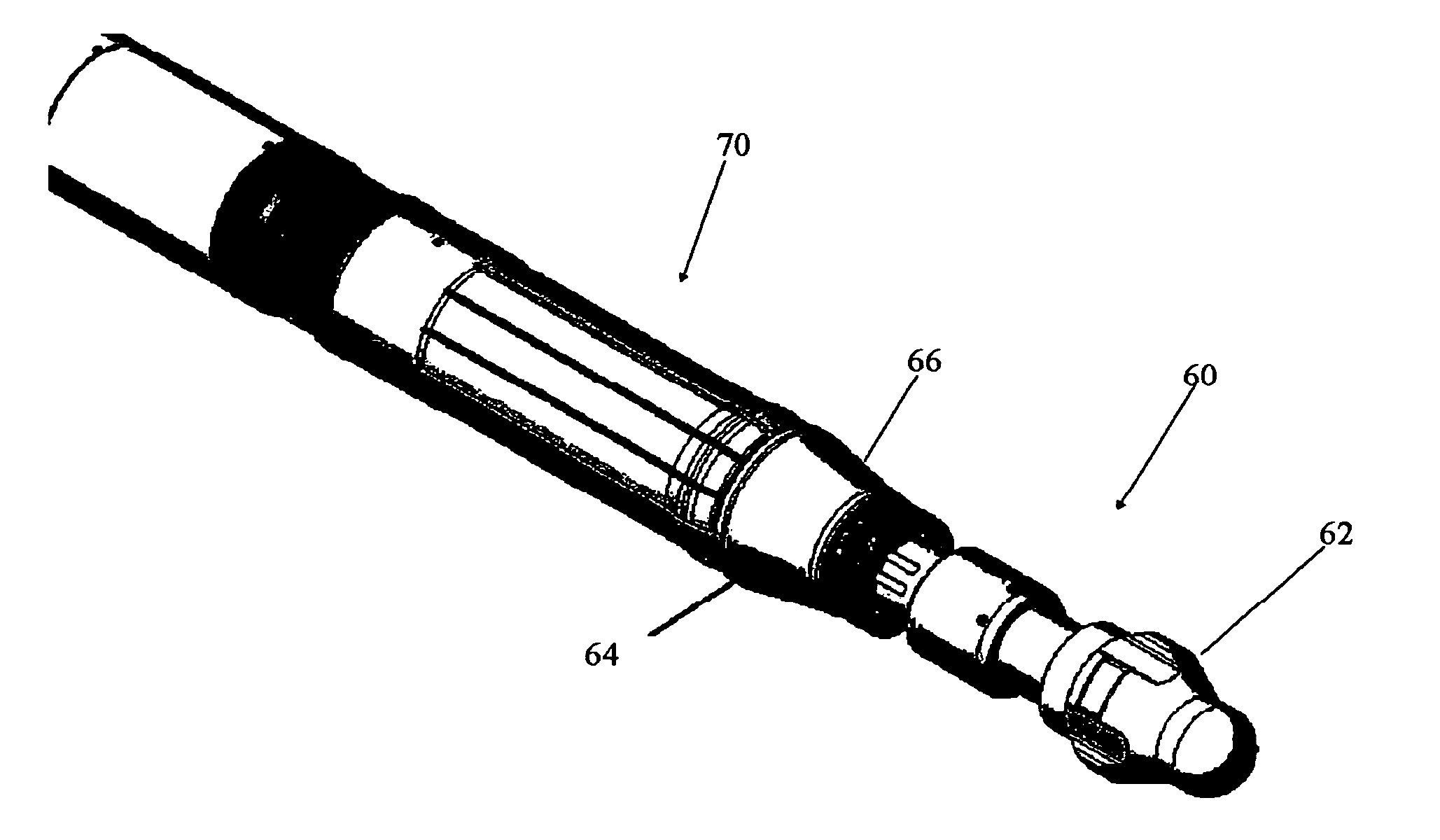
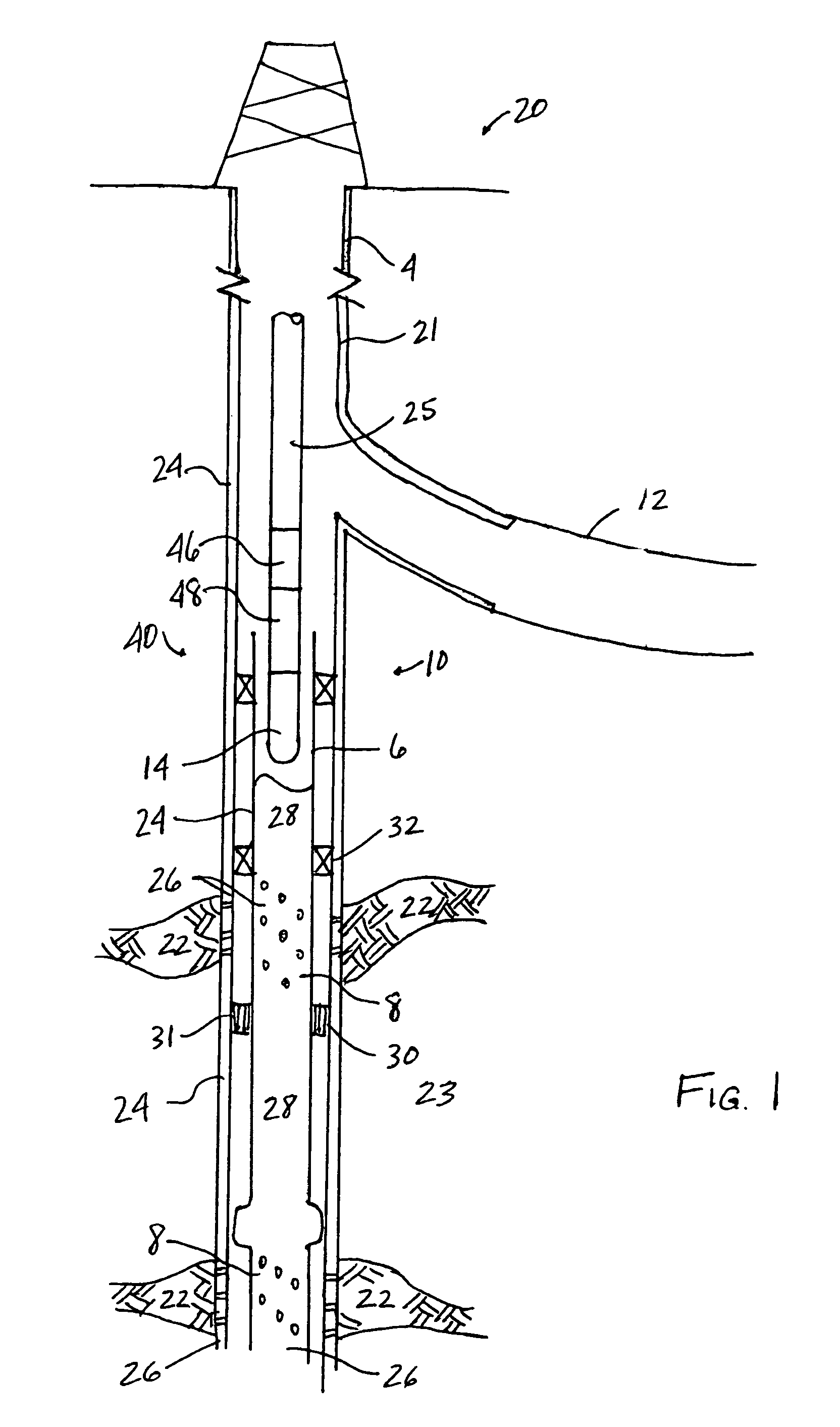
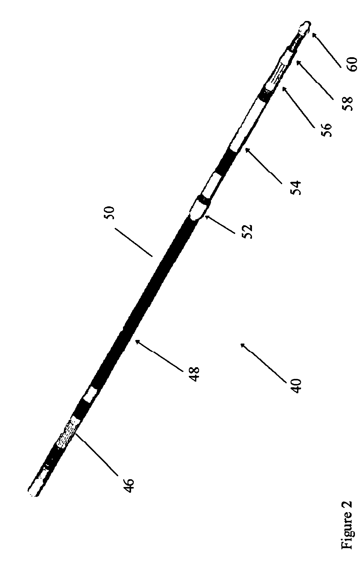
[0013]The tool is operated using fluid flow pumped, preferably from the surface of the well. The fluid flow is used to operate a stroking piston assembly to advance the expansion tool. A portion of the flow is used to operate the variable-diameter expansion cone tool. The flow is split at a control valve and a pressure drop is created across an orifice. The fluid flow split to a piston assembly operates to move the pistons, which in turn move a wedge which expands the variable-diameter cone. When a restriction is encountered, the tool assembly slows and / or stops, thereby increasing fluid pressure across the control valve. The biased valve closes at a pre-determined pressure and cuts flow to the piston assembly of the cone. The variable-diameter cone retracts until forward motion is achieved. Once motion resumes, the pressure across the control valve drops and pressure is restored to the cone pistons.

Problems solved by technology

When a restriction is encountered, the tool assembly slows and / or stops, thereby increasing fluid pressure across the control valve.

Method used


Image

  • Variable diameter expansion tool and expansion methods
  • Variable diameter expansion tool and expansion methods
  • Variable diameter expansion tool and expansion methods

Examples


Embodiment Construction

[0023]The present inventions are described by reference to drawings showing one or more examples of how the inventions can be made and used. In these drawings, reference characters are used throughout the several views to indicate like or corresponding parts. In the description which follows, like or corresponding parts may be marked throughout the specification and drawings with the same reference numerals, respectively. The drawings are not necessarily to scale and the proportions of certain parts have been exaggerated to better illustrate details and features of the invention. In the following description, terms such as “upper,”“upward,”“lower,”“downward,”“above,”“below,”“downhole,”“uphole,”“longitudinal,”“lateral,” and the like, as used herein, shall mean in relation to the bottom or furthest extent of, the surrounding wellbore even though the wellbore or portions of it may be deviated or horizontal. Correspondingly, the transverse, axial, lateral, longitudinal, radial, etc., or...


PUM


Abstract

The present inventions relate to improved apparatus and methods for radially expanding tubulars, such as tubing, casing and sand-control screen assemblies in a subterranean oil or gas well, and more specifically, to a variable diameter expansion tool for expanding downhole tubulars to varying diameters. In general, the inventions provide apparatus and methods for radially expanding a tubular, such as pipe, tubing, screen or screen assembly, deployed in a subterranean well by moving an expansion tool axially through the well. An automatically infinitely variable-diameter expansion cone tool is provided. A variable-diameter cone is provided, movable between an expanded position and a retracted position. The cone is enlarged to its expanded position and advanced through expandable components until a restriction is reached. At the restriction, the variable-diameter cone automatically retracts enough to allow the tool to continue advancing through the wellbore. When the restriction is past, the variable-diameter cone enlarges again to its expanded position.

Description

CROSS-REFERENCE TO RELATED APPLICATIONS[0001]NoneSTATEMENT REGARDING FEDERALLY SPONSORED RESEARCH OR DEVELOPMENT[0002]NoneREFERENCE TO MICROFICHE APPENDIX[0003]Not applicableTECHNICAL FIELD[0004]The present inventions relate to improved apparatus and methods for radially expanding tubulars, such as tubing, casing and sand-control screen assemblies in a subterranean oil or gas well, and more specifically, to a variable diameter expansion tool for expanding downhole tubulars to varying diameters.BACKGROUND OF THE INVENTIONS[0005]It is common in modern oil field operations and completions to place expandable tubular components 2 downhole in a subterranean well 20, such as that seen in FIG. 1. The expandable components 2 include expandable tubulars and expandable devices which are placed downhole and, once in place, expanded to a desired size. The expandable components can be casing 4, tubing 6, sand-control screen assemblies 8 and other expandable tubulars known in the art. The tubular...

Claims


Application Information

Patent Timeline
Patent Type & Authority Patents(United States)
IPC IPC(8): E21B23/01
CPCE21B43/105
Inventor GANO, JOHN C.JACKSON, TANCE
Owner HALLIBURTON ENERGY SERVICES INC
Learn More