
Controllably Stiffenable Tube

Inactive Publication Date: 2011-02-17
EPFLEX FEINWERKTECHN
View PDF19 Cites 31 Cited by
  • Summary
  • Abstract
  • Description
  • Claims
  • Application Information

AI Technical Summary

Benefits of technology

[0006]WO 2005 / 042078 A1 discloses a device, especially a lock or a catheter, for the at least partial insertion into a body canal, having an oblong, outer enveloping body, an oblong inner body surrounded by the latter on the circumference side at least in sections and a control device formed by the arrangement and construction of the enveloping body and of the inner body itself. The control device is permits a relative movement between the enveloping body and the inner body such that it can be controlled in a targeted manner or at least making this relative movement more difficult. The control device particularly is constructed such that the friction between the enveloping body and the inner body can be controlled mechanically and / or by a pressure or a vacuum, electric polarization, magnetization and / or by a molecular alteration. The material of the enveloping body and the inner body preferably has a flexible but distortion-proof construction.
[0008]An object of the present invention is to provide a tube that can be stiffened in an improved controlled or targeted manner, and be returned to its less stiff condition.
[0012]The tube configuration according to the present invention such that it is changed to its flexurally stiffer state by overpressure and not by underpressure has, among others, advantages with respect to a greater freedom of choice for the shape and the material of the flexible stiffening elements and the handling of the tube when in use. In addition, the equipment expenditures for providing overpressure are generally lower than for providing an underpressure resulting in comparably high pressure forces. Furthermore, an admission of overpressure normally can be caused with clearly shorter reaction times than an admission of underpressure.
[0021]As a further development of the invention, the longitudinal rod-type element(s) or inner member(s), which form at least a portion of the flexible stiffening elements, are those made of a flat-wire or round-wire material or of a stranded material or a rope material. The at least one inner member may also be implemented as a tubular braiding which can be radially expanded to the required extent and is stable with respect to longitudinal force. Corresponding flat-wires or round-wires, strands, or ropes or tubular braidings, which operate as flexible longitudinal rod-type elements or inner members, may extend particularly along the entire or at least the predominant length of the tube in the axial direction and, in the process, absorb tensile forces and, in this manner, stabilize the longitudinal course of the outer sleeve and thus of the tube as a whole also in curved sections in a stiffening fashion.

Problems solved by technology

The control device is permits a relative movement between the enveloping body and the inner body such that it can be controlled in a targeted manner or at least making this relative movement more difficult.
As a result, a stiffening of the entire device is to be caused.
In addition, the equipment expenditures for providing overpressure are generally lower than for providing an underpressure resulting in comparably high pressure forces.
This may further result in such tensile forces that the tube is stiffened in a position which represents no stable position in the force-free unstiffened state, so that the tube attempts to move from its stiffened position into its initial position which results in corresponding force loads for one or more of the flexible stiffening elements.

Method used


Image

  • Controllably Stiffenable Tube
  • Controllably Stiffenable Tube
  • Controllably Stiffenable Tube

Examples


Embodiment Construction

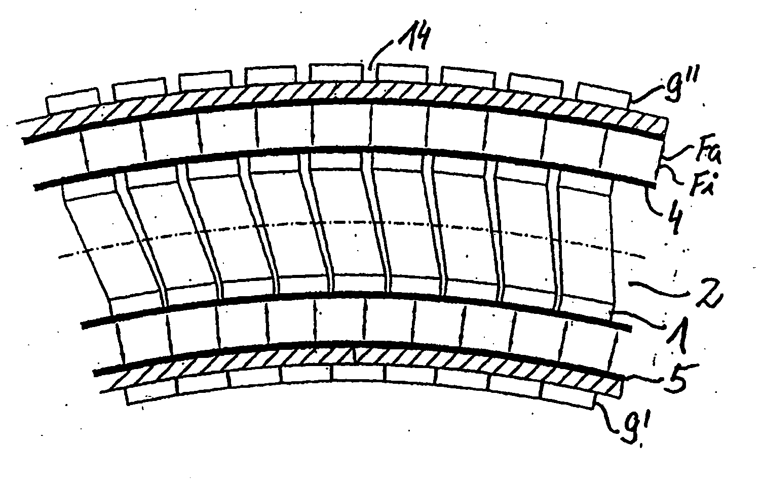
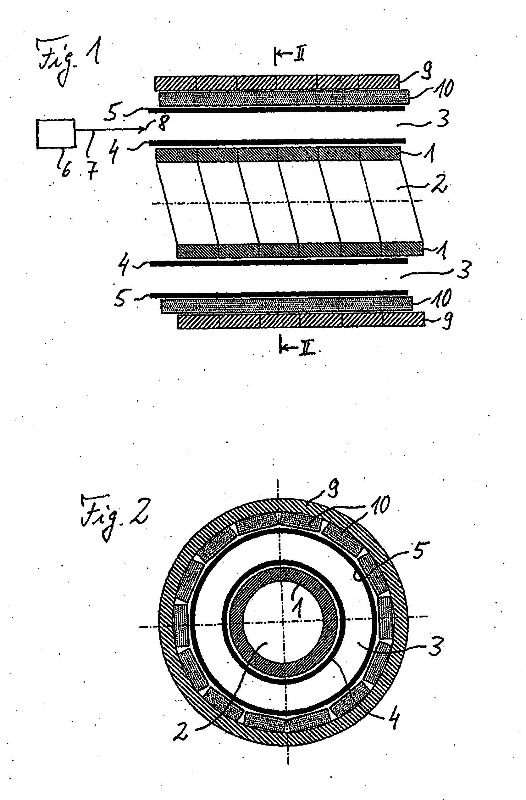
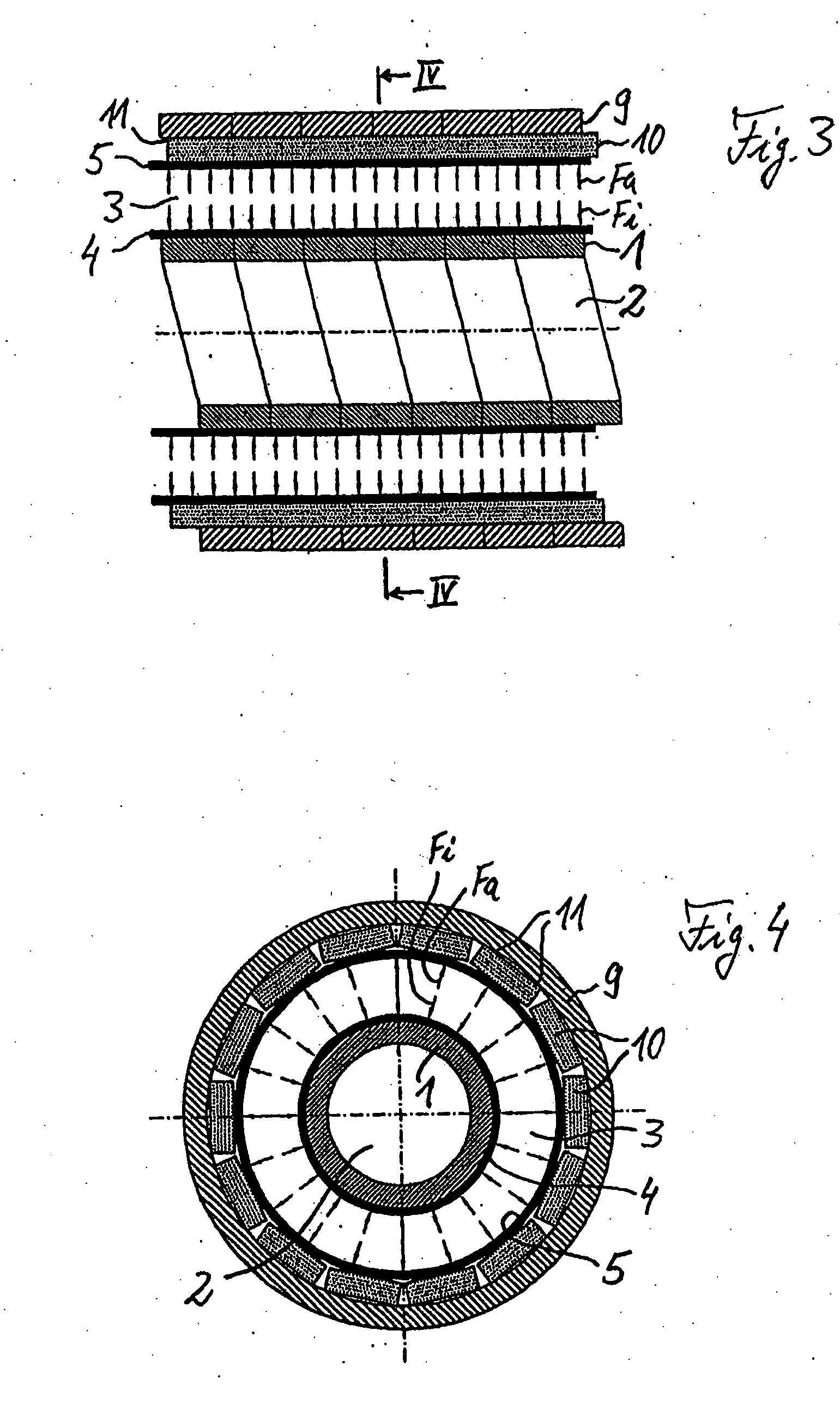
[0035]FIGS. 1 to 5 illustrate a first embodiment of a tube that can be stiffened, FIGS. 1 and 2 relating to a pressure-relieved, more flexible initial state of the tube, and FIGS. 3 to 5 relating to a pressure-loaded stiffened state of the tube. FIGS. 1 and 3 each are longitudinal sectional views of a linear axial portion of the tube; FIGS. 2 and 4 each being cross-sectional views of the tube; and FIG. 5 being a longitudinal sectional view of a curved axial portion of the tube. The dimensions of all illustrated elements of the tube are not necessarily true to scale but are each displayed for sufficiently clearly indicating the significance of these elements for the invention. This also applies to the additional hose variations illustrated in FIGS. 6 to 11.

[0036]All illustrated embodiments can be used, for example, as catheters for medical applications. Furthermore, tubes according to the invention that can be stiffened can also be used for other medical and non-medical purposes wher...


PUM


Abstract

A tube that can be stiffened in a controlled manner has a pressure channel for controllable production of a stiffening overpressure by introduction of a pressure medium. The tube has several flexible stiffening elements, of which at least one is stable with respect to tensile force and which are pressed onto one another when acted upon by the stiffening overpressure with the result that the tube is changed from a more flexible state to a more flexurally stiff state. A channel is separate from the pressure channel and, in the stiffened state of the tube, forms a working channel whose course corresponds to the tube shape.

Description

BACKGROUND AND SUMMARY OF THE INVENTION[0001]The present invention relates to a tube that can be stiffened in a controlled manner, usable particularly as a catheter in the medical field and the like.[0002]Conventional catheters used in the medical field are relatively stiff because a corresponding stiffness is required in the operating or working position in which the catheter is pushed into a tissue canal of a human or animal body, such as a vein or artery. For inserting such a conventional catheter, a guide wire is therefore normally first introduced into the tissue canal, along which the catheter is then pushed following the guide wire.[0003]For the foregoing purpose, WO 2004 / 035124 A1 suggests guide wires which can be stiffened in a controlled manner and which have several strands of wire that can be acted upon by magnetic attraction forces by generating magnetic fields in order to change the guide wire into a flexurally stiff condition. By deactivating the magnetic fields, the ...

Claims


Application Information

Patent Timeline
IPC IPC(8): A61M25/00
CPCA61M25/0023A61M2025/0063A61M25/0043
Inventor UIHLEIN, BERNHARD
Owner EPFLEX FEINWERKTECHN
Learn More