Oral Implant Placement System and Method

a technology for placing and installing dental implants, applied in the field of dental implants, can solve the problems of excessive wear and tear, loss of teeth, and negative effect on eating habits

Inactive Publication Date: 2011-02-10
IMMEDIATE IMPLANT TECH
View PDF19 Cites 11 Cited by
  • Summary
  • Abstract
  • Description
  • Claims
  • Application Information

AI Technical Summary

Benefits of technology

[0008]An oral implant system and method are disclosed according to an embodiment of the present invention. The system comprises a positioning tool, a transfer band, a transfer screw and a transfer drill, all used in cooperation to provide for the accurate placement of a dental implant parallel to other implants and or existing teeth and at predetermined depths. Impressions are made of the patient's mouth and a model is made of the patient's maxilla and mandible. The model is marked for implant position, depth and size on either the maxilla or the mandible. Apertures are drilled into the model using the positioning tool, then analogs are installed into the model using the positioning tool and a surveyor. A final restoration prosthetic is then fabricated. Transfer bands are coupled to the analogs with transfer screws and a lower surgical stent portion conforming to the patient's mandible is fabricated. An upper surgical stent portion conforming to the patient's maxilla is also fabricated. The finished surgical stent, comprising the lower and upper stent portions, is fitted to the patient's occlusion and secured. A transfer drill is rotated and slidably inserted through chamfered openings in the transfer bands to drill apertures into the patient's maxilla or mandible as appropriate, the apertures having a predetermined position and depth. Implants are installed into the apertures and the surgical stent is removed. Finally, the finished restoration prosthetic is secured to the implants.
[0009]One embodiment of the present invention may be an oral implant placement system comprising a surgical stent having a first portion and a detachable second portion, the first and second portions being sized and shaped to conform to an occlusion in a select region of a patient's mouth. At least one generally cylindrical transfer band is embedded in the first surgical stent portion, the transfer band having first and second opposing generally planar ends and an opening extending between the ends, the opening including an interior chamfer proximate the second end. The system may include a transfer drill having a chamfered shank portion sized and shaped to be slidably received by the opening of the transfer band. The surgical stent is positioned in the patient's mouth in conformance with the occlusion and the first su

Problems solved by technology

Teeth are lost for a variety reasons, such as tooth decay, root canal failure, periodontitis (gum disease), trauma to the mouth, excessive wear and tear, and congenital defects.
Additionally, biting irregularities caused by tooth loss can have a negative effect on eating habits.
This can lead to secondary health problems, such as malnutrition.
Dental implant stents and other devices presently used by surgeons to place dental implants in a patient's mouth do not have features that allow the surgeons to place a dental implant parallel to other implants and / or existing teeth and at precise, predetermined depths within the arch of the mandible or maxilla.
A similar drawback occurs with dental implants used as supporting members for the development of a dental prosthesis.
When dental implants are not placed parallel to other dental implants, final restoration prostheses are much more difficult to manufacture and the fit and longevity of a final restoration is reduced.
This often increases the amount of time required for the patient to heal and recover from the procedure.

Method used


Image

  • Oral Implant Placement System and Method
  • Oral Implant Placement System and Method
  • Oral Implant Placement System and Method

Examples


Embodiment Construction

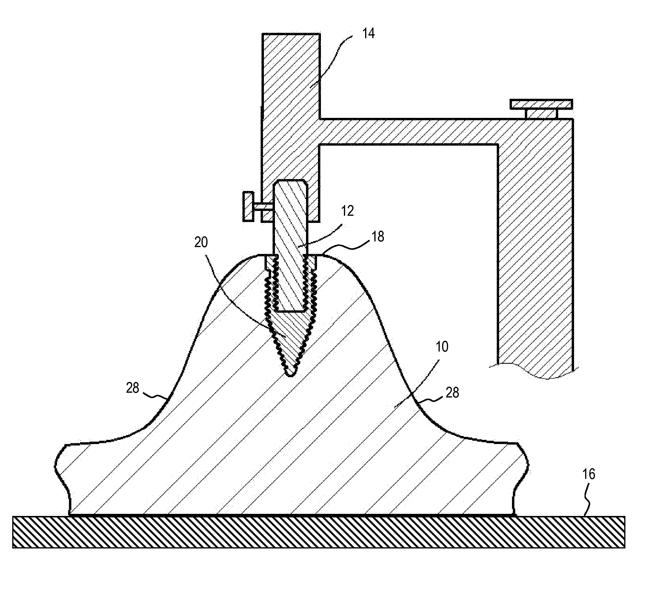
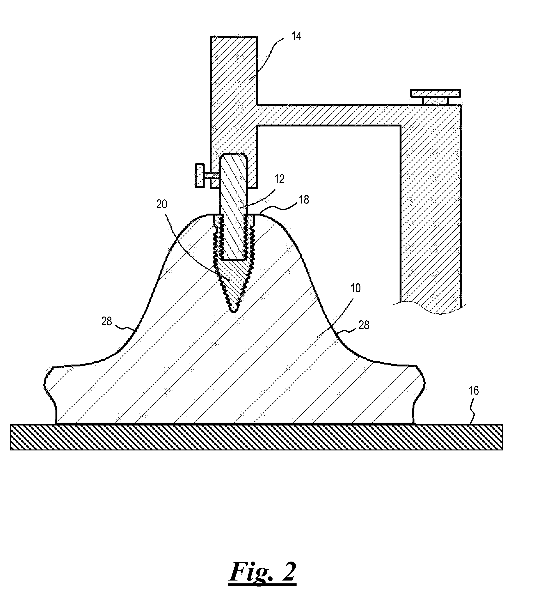
[0033]In the discussion that follows, like reference numerals are used to refer to like structures in the various figures.

[0034]The general arrangement of a process for producing an oral implant is shown in FIG. 1. Reference should be made to this figure in combination with other figures referred to in the discussion that follows.

[0035]At step s100 a set of impressions are made of the maxilla and / or mandible of a patient's mouth, particularly the patient's dental arch in the region of the patient's mouth selected for the installation of one or more dental implants. The object of making an impression is to accurately relate an analog of the implant or implant abutment to other structures in the dental arch. A malleable impression material is typically pressed into a tray, and the tray is then inserted in the patient's mouth. The patient bites into the impression material to create an impression of his or her maxilla and / or mandible in the material. Typical impression materials may in...


PUM


Abstract

An oral implant system and method. The system comprises a positioning tool, a transfer band, a transfer screw and a transfer drill to provide for accurate placement of a dental implant parallel to other implants and or existing teeth and at predetermined depths. A model is made of the patient's maxilla and mandible. The model is marked for implant position, depth and size. Holes are drilled in the model for implant analogs using the positioning tool. The analogs are installed into the model using the positioning tool and a surveyor. Transfer bands are coupled to the analogs and a surgical stent portion is fabricated. The surgical stent is fitted to the patient's occlusion, secured, and then utilized to accurately drill apertures into the patient's maxilla or mandible. The implants are installed into the apertures and the surgical stent is removed. A final restoration is secured to the implants.

Description

[0001]This application is a continuation-in-part of U.S. patent application No. 12 / 428,450, filed Apr. 22, 2009, which is a continuation-in-part of U.S. patent application No. 12 / 148,996, filed Apr. 24, 2008; U.S. patent application No. 11 / 807, 360, filed May 29, 2007; U.S. patent application No. 11 / 807,366, filed May 29, 2007; U.S. patent application No. 11 / 807, 377, filed May 29, 2007; and U.S. patent application No. 11 / 975,586, filed Oct. 22, 2007, the entire contents of each being expressly incorporated herein by reference thereto.FIELD[0002]The present invention relates generally to dental implants, in particular to a system and method for positioning and installing dental implants in a patient's mouth.BACKGROUND[0003]Teeth are lost for a variety reasons, such as tooth decay, root canal failure, periodontitis (gum disease), trauma to the mouth, excessive wear and tear, and congenital defects. Patients who have lost teeth are often reluctant to smile or talk. Additionally, bitin...

Claims


Application Information

Patent Timeline
IPC IPC(8): A61C8/00A61C13/38
CPCA61C8/0089A61C1/084
Inventor DUNCAN, GARY A.
Owner IMMEDIATE IMPLANT TECH
Why Eureka
Try Eureka