
Sealed rectangular battery and battery module using same

a rectangular battery and battery module technology, applied in the direction of cell components, flat cell grouping, sustainable manufacturing/processing, etc., can solve the problem of limited space for battery installation, and achieve the effect of reducing the swelling of the cell stacked body in respective directions laterally thereof, facilitating installation, and improving mechanical strength of the side face pla

Active Publication Date: 2011-02-03
KAWASAKI MOTORS LTD
View PDF3 Cites 45 Cited by
  • Summary
  • Abstract
  • Description
  • Claims
  • Application Information

AI Technical Summary

Benefits of technology

[0009]Also, where a plurality of rectangular batteries are to be stacked in a plurality so that they can be used as a battery module, there is a need to fasten and fix the cell stacked body in a direction conforming to the direction of stacking in order to suppress the inflation of the cell stacked body, in which unitary cells are stacked, in the direction conforming to such lamination. Considering the space for installation of the battery module in the above described vehicle and the energy efficiency in driving the vehicle, the use of members for fastening and fixing the cell stacked body is required to be dispensed as far as possible and the battery module is required to be assembled compact in size and small in weight.
[0027]The battery module in accordance with one embodiment of the present invention may additionally include a pressure regulating mechanism for discharging gases, developed inside the cell stacked body, to the outside in the event of increase of an internal pressure of the cell stacked body to a predetermined value. The use of the pressure regulating mechanism makes it possible to further increase the pressure resistance of the battery.

Problems solved by technology

In general, where the battery is to be mounted for use in driving the vehicle, the battery is often mounted as a component additional to the conventional mechanism and the space for installation of the battery is limited.

Method used


Image

  • Sealed rectangular battery and battery module using same
  • Sealed rectangular battery and battery module using same
  • Sealed rectangular battery and battery module using same

Examples


Embodiment Construction

[0046]While embodiments of the present invention will be described in detail with particular reference to the accompanying drawings, those embodiments should not be construed as limiting the scope of the present invention.

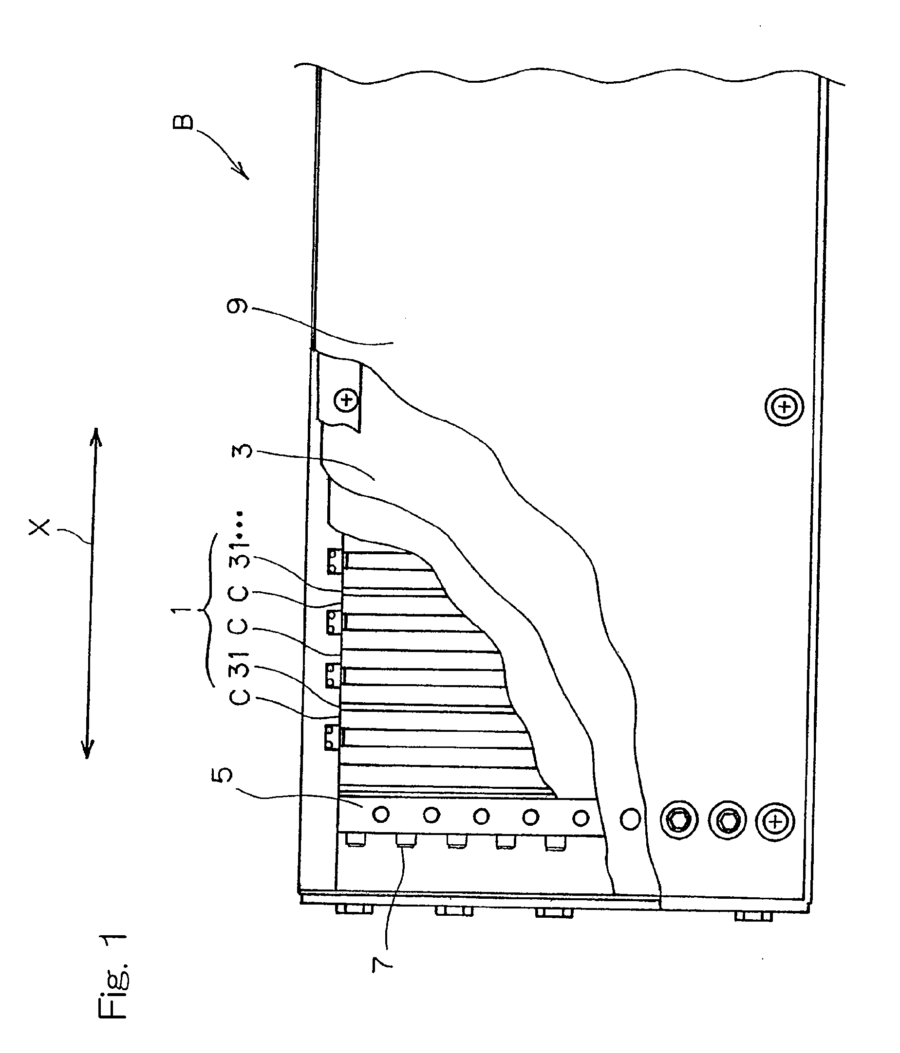
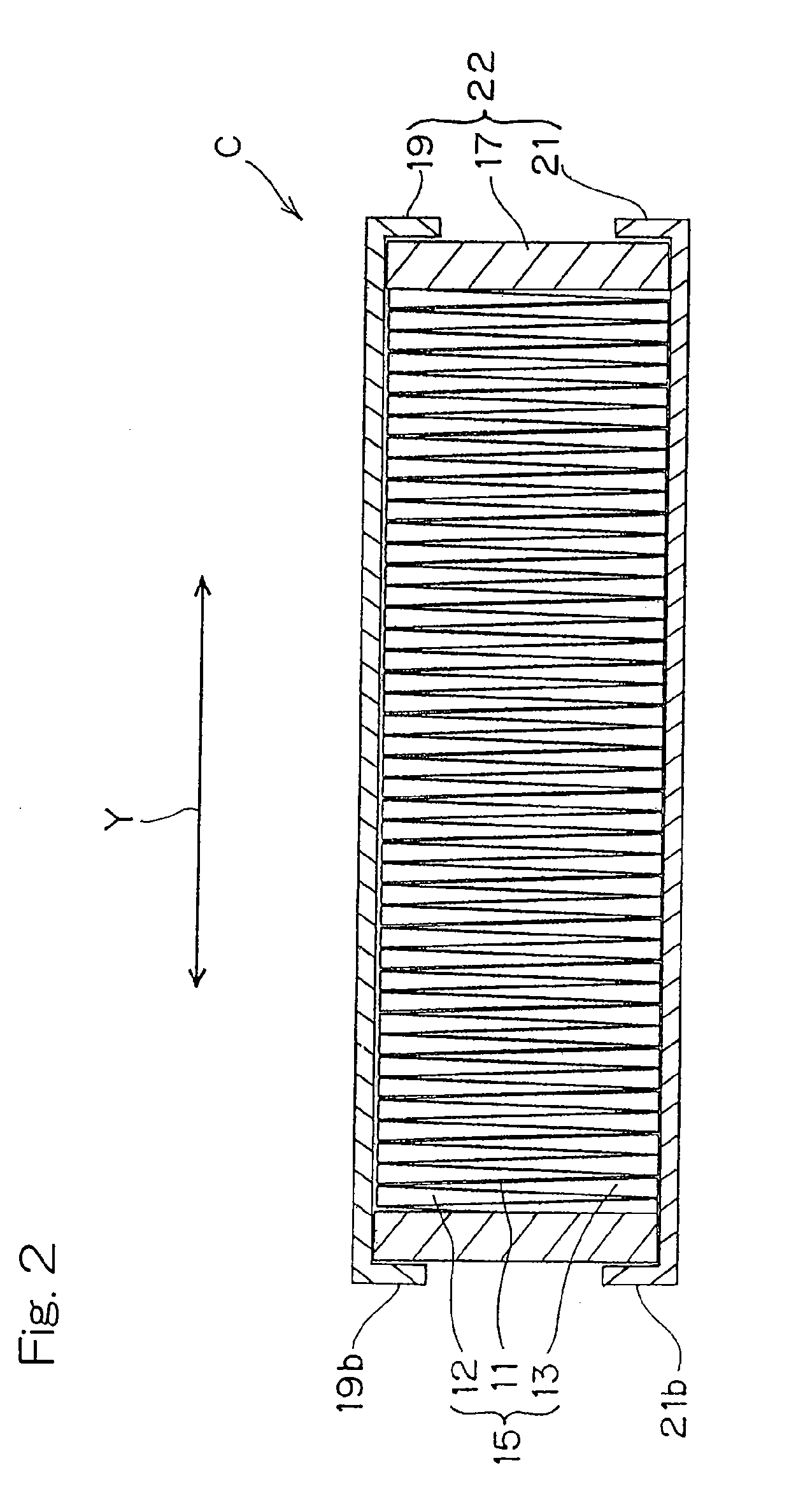
[0047]FIG. 1 is a partially cutaway side view schematically showing the structure of a battery module B according to one embodiment of the present invention. The illustrated battery module B is of a type that is mounted on, for example, a railcar and includes a cell stacked body 1, made up of major component parts including a plurality of (for example, 30 in the instance as shown) unitary cells C in the form of sealed rectangular batteries, which are stacked together in a direction conforming to the direction of thickness of each of the unitary cells C, side plates 3, compressing plates 5 and clamping bolts 7 used to fasten and fix the cell stacked body 1 in a direction conforming to the direction X of stacking. Those major component parts are enclosed within a cas...


PUM


Abstract

A sealed rectangular battery excellent in volumetric efficiency and pressure resistance is provided. The sealed rectangular battery includes an electrode group having a positive electrode and a negative electrode and a cell casing for accommodating therein the electrode group and an electrolyte solution, which casing includes a rectangular frame member, a first lid member and a second lid member. Each of the first and second lid members includes a body portion for covering one of the openings of the frame member, and a side portion formed so as to protrude from the body portion substantially along at least one set of sides opposite to each other.

Description

CROSS REFERENCE TO THE RELATED APPLICATION[0001]This application is a continuation application, under 35 U.S.C. §111(a), of international application No. PCT / JP2009 / 001254, filed Mar. 19, 2009, which claims priority to Japanese patent application No. 2008-103901, filed Apr. 11, 2008, the disclosure of which is incorporated by reference in its entirety into this application.BACKGROUND OF THE INVENTION[0002]1. Field of the Invention[0003]The present invention relates to a sealed rectangular battery having a pressure resistance to the internal pressure of the battery despite a simplified structure employed therein and, also, to a battery module using the plurality of sealed rectangular batteries.[0004]2. Description of the Related Art[0005]For the shape of the sealed battery, cylindrical shape has long been widely adopted. In the cylindrical battery, not only can a simplified structure, in which positive and negative electrode plates are wound in a cylindrical form with a separator int...

Claims


Application Information

Patent Timeline
IPC IPC(8): H01M6/46H01M2/02H01M2/12H01M50/10H01M50/159H01M50/209H01M50/55H01M50/553H01M50/567
CPCH01M2/024H01M2/1077H01M2/0478H01M2/18H01M2/305H01M10/0413H01M10/0459H01M10/0481H01M10/0486H01M10/345H01M10/48H01M10/5004H01M10/5016H01M10/5032H01M10/5059H01M10/5071H01M2/043H01M10/625H01M10/647H01M10/6557H01M10/6565H01M10/613Y02E60/10H01M50/10Y02P70/50H01M50/159H01M50/209H01M50/55H01M50/553H01M50/567H01M50/103
Inventor TSUTSUMI, KAZUONISHIMURA, KAZUYA
Owner KAWASAKI MOTORS LTD
Learn More