
Organic synthesizer

Inactive Publication Date: 2011-02-03
SIBATA SCI TECH
View PDF10 Cites 1 Cited by
  • Summary
  • Abstract
  • Description
  • Claims
  • Application Information

AI Technical Summary

Benefits of technology

[0037]As described above, the organic synthesizer according to the first invention is capable of achieving stable rotations from a lower speed rotation to a higher speed rotation and easily setting the numbers of revolutions individually without suffering any influence from an adjacent magnet.
[0038]In the organic synthesizer according to the second invention, it is configured capable of being synthesized with reaction conditions set for other reaction vessels. Accordingly, it is possible to provide an organic synthesizer capable of easily setting a reaction condition for one reaction vessel same as those for other reaction vessels.
[0039]The organic synthesizer according to the third invention is possible to provide an organic synthesizer capable of stirring a reagent within a reaction vessel without bringing a stirrer in contact with the reaction vessel.
[0040]The organic synthesizer according to the fourth invention is possible to provide an organic synthesizer capable of matching the central axis of a reaction vessel with the center of rotation of a rotating means, when the reaction vessel is housed, even if a gap is formed between an outer circumferential surface of the reaction vessel and an inner circumferential surface of a reaction vessel container.
[0041]The organic synthesizer according to the fifth invention is possible to provide an organic synthesizer capable of a pressure reaction and an atmospheric reaction in a single organic synthesizer.
[0042]The organic synthesizer according to the sixth invention is possible to provide an organic synthesizer capable of detachment / attachment of a reaction vessel from / to the organic synthesizer without imposing no load on a gas supply / discharge pipe.THE

Problems solved by technology

In this case, magnetic forces from adjacent rotary magnet units 316A-316E mutually affect and cause a problem because the stirring speeds cannot be adjusted easily.
This is a first problem.
In addition, in the above organic synthesizer, even if a reaction condition such as a reaction temperature for one reaction vessel 306 is made same as those for other reaction vessels, the need for setting respective reaction conditions for the associated reaction vessels 306 results in a complicated setting work therefor.
This is a second problem.
Further, the use of reaction vessels of PTFE (Poly Tetra Fluoro Ethylene) results in abraded reaction vessels.
This is a third problem.
The reaction vessels 306 cannot be molded easily, however, such that they can be housed tightly in the housing portions of the pressure-proof vessels 308.
In addition, the friction with the stirrer and the counteraction of the reaction liquid in the reaction vessel in accordance with the rotation of the stirrer may cause the reaction vessel to rotate in synchronization with the stirrer to result in insufficient stirring.

Method used


Image

  • Organic synthesizer
  • Organic synthesizer
  • Organic synthesizer

Examples


first example

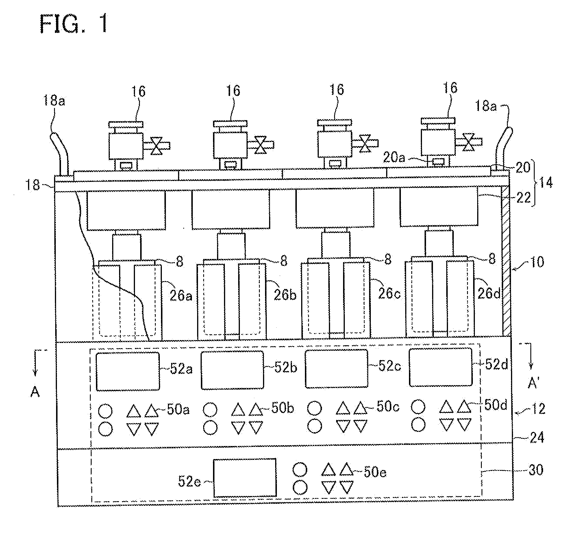
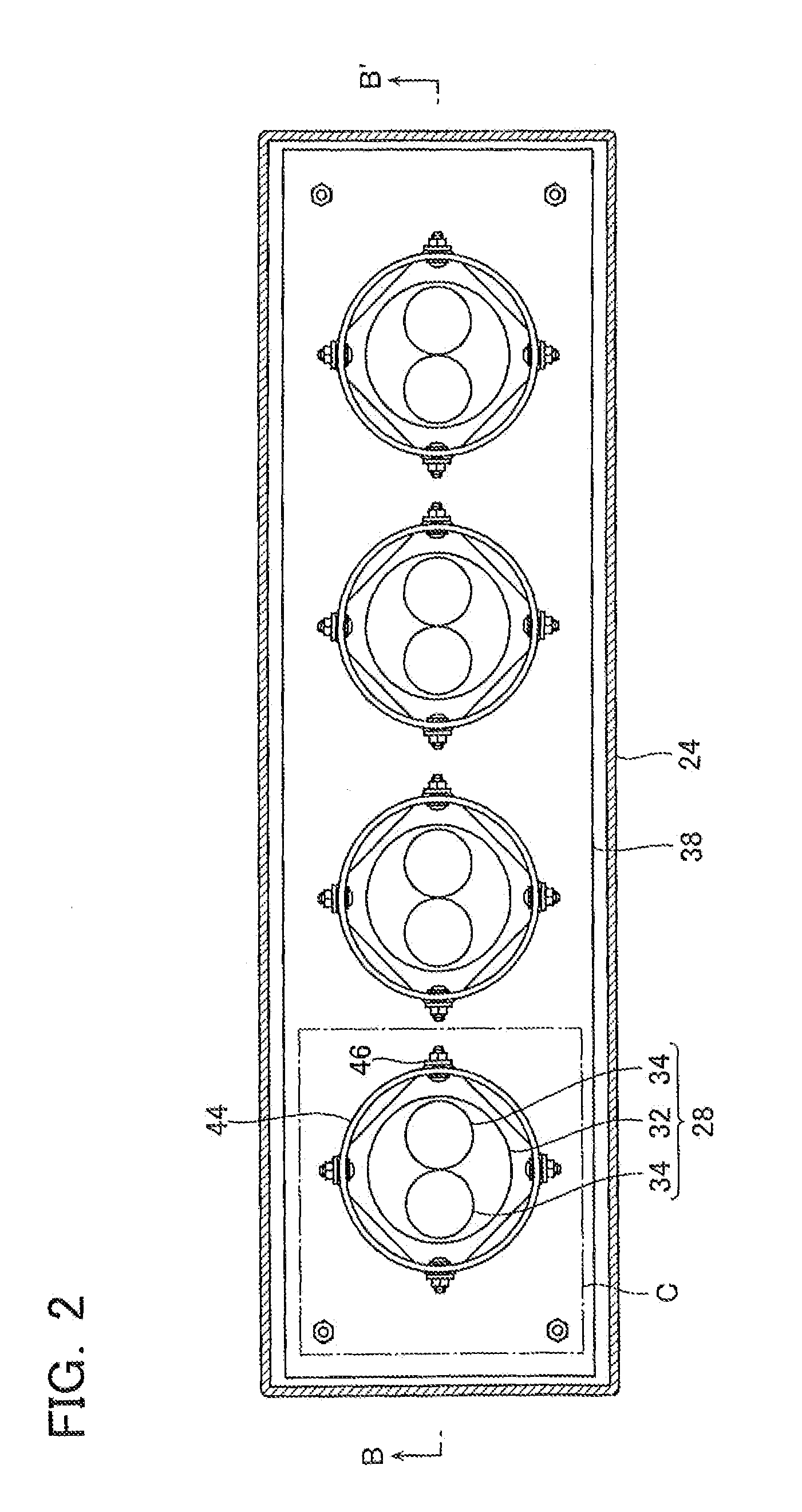
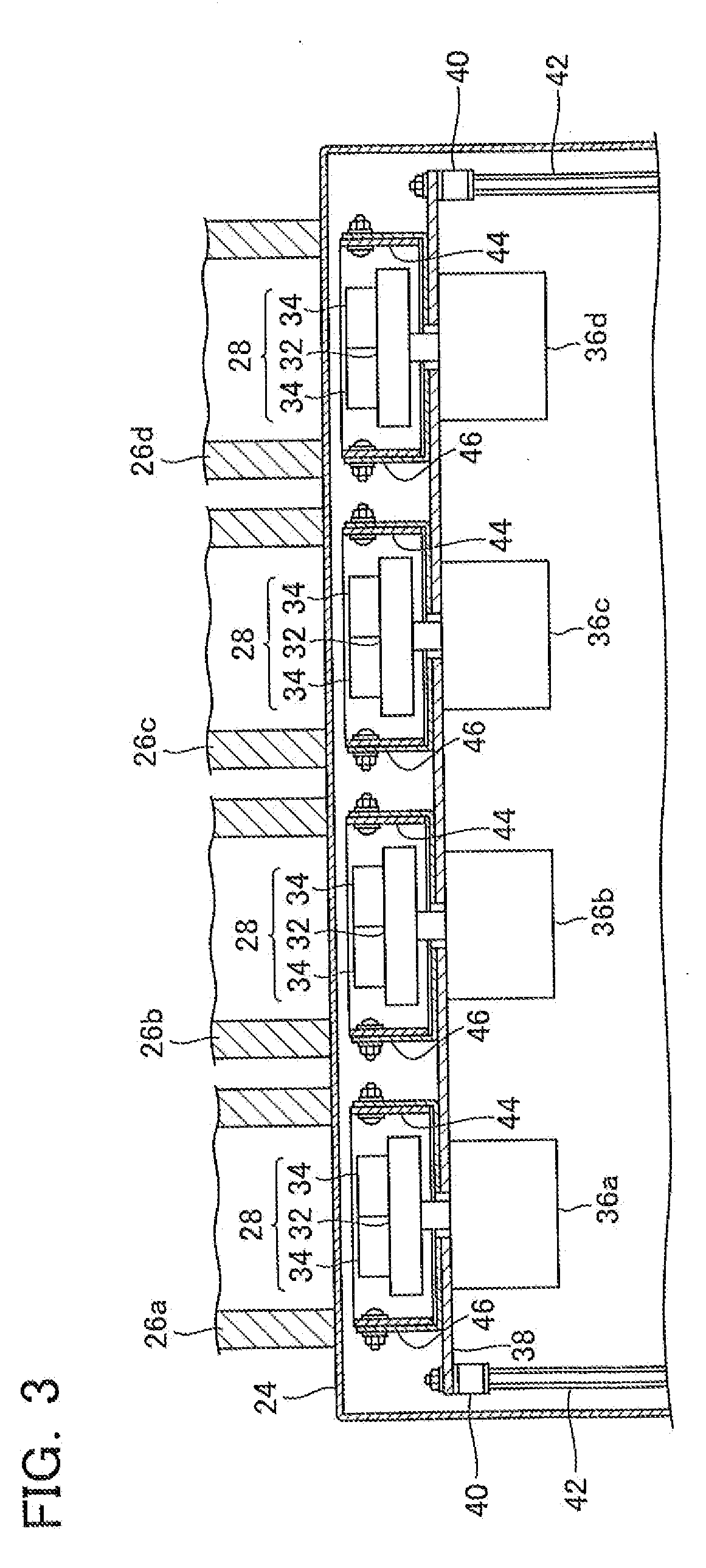
[0044]Referring to FIGS. 1-7, an organic synthesizer according to an example of a first invention and a second invention (hereinafter referred to as a “first example”) is described. FIG. 1 is a front schematic view showing the organic synthesizer according to the first example in use. The organic synthesizer according to the present example comprises a reaction vessel support 10 capable of supporting four reaction vessels 8, and a stirring unit 12 operative to stir samples in the reaction vessels 8 gripped by the reaction vessel support 10. The reaction vessel support 10 and the stirring unit 12 are configured separable from each other.

[0045]The reaction vessel supports 10 are provided for the associated reaction vessels 8 and include four reaction vessel holders 14 connected to the respective reaction vessels 8, four reagent adders 16, and a frame 18 for supporting the four reaction vessel holders 14. The reaction vessel holders 14 include four top plates 20, and four returning blo...

second example

Alternative To Second Example

[0068]Referring next to FIGS. 12-17C, an organic synthesizer according to an alternative to the second example is described. The organic synthesizer according to the alternative to the second example of the present invention mainly, like the second example, comprises a reaction vessel support capable of supporting reaction vessels, a pressure regulating unit for regulating pressures in the reaction vessels, and a stirring unit operative to stir samples in the reaction vessels (not shown).

[0069]The alternative to the second example is different from the second example particularly in the structure of pressure-proof vessels 116 for housing reaction vessels 114 therein hermetically, and in the structure of stirring members 120 having upper ends rotatably supported at the upper portions of the reaction vessels 114 and lower ends immersed into reagents in the reaction vessels 114 and configured capable of gripping stirrers 118. The following description is gi...

third example

Second Alternative To Third Example

[0100]An organic synthesizer according to a second alternative to the third example is described next based on FIGS. 27A and 27B. As shown in FIG. 27A, the organic synthesizer according to the second alternative to the third example includes rectangular openings 220a-220d and rotatable L-shaped hooks 222a-222d, instead of the inverted L-shaped openings 194a-194d, for supporting the first through fourth gas supply / discharge pipes 174a-174d, different from the third example. In such the arrangement, it is possible to shift the first through fourth gas supply / discharge pipes 174a-174d to the left side above the rectangular openings 220a-220d, as from the state of FIG. 27A to the state shown in FIG. 27B, and then hook the pipes on hooks 222a-222d, thereby leaving the pipes in place. Namely, the organic synthesizer according to the second alternative to the third example can move upward from the position connected to the pressure-proof vessel 166, and m...


PUM


Abstract

To provide an organic synthesizer that can conduct a pressure reaction and an atmospheric reaction in one organic synthesizer and can realize attachment of reaction vessels to the organic synthesizer and detachment of the reaction vessels from the organic synthesizer without applying any load to gas supply / discharge pipes.[Means For Solving Problems] An organic synthesizer comprising a reaction vessel support part (160), which can support two or more reaction vessels, and pressure regulation means (164) for regulating the pressure within the reaction vessel supported by the reaction vessel support part (160) by supplying / discharging gas. Two or more pressure regulation means (164) are provided for each reaction vessel supported by the reaction vessel support part (160). At least one pressure regulation means (164A) in the two or more pressure regulation means (164) is constructed so as to be detachable from and attachable to the other pressure regulation means (164B). The pressure regulation means (164) comprises gas supply / discharge pipes (174a to 174d) and openings (194a to 174d) for supporting the gas supply / discharge pipes (174a to 174d). The gas supply / discharge pipes (174a to 174d) are constructed so that a part near the front end can be flexed in a vertical direction and in a lateral direction and are connected to the supported reaction vessels for gas supply and discharge.

Description

TECHNICAL FIELD[0001]The present invention relates to an organic synthesizer for reagent stirring, heating and pressure regulating in reaction vessels to synthesize reagents contained in the reaction vessels.BACKGROUND ART[0002]An organic synthesizer has been used to synthesize many types of samples at once under an identical condition or different conditions and examine the synthesized samples in unison. Examples of such the organic synthesizer include an organic synthesizer of the atmospheric type that stirs and heats samples within reaction vessels at normal pressure to synthesize the samples contained within the reaction vessels (see Patent Document 1), and another organic synthesizer of the pressure regulating type that is capable of regulating pressures in the reaction vessels, such as pressurizing and depressurizing, in addition to stirring / heating the samples. The organic synthesizer of the pressure regulating type mainly comprises, as shown in FIGS. 28 and 29, a reaction ve...

Claims


Application Information

Patent Timeline
IPC IPC(8): B01J19/18B01J19/00
CPCB01F7/001B01J2219/0072B01F7/00141B01F7/003B01F7/00558B01F13/0827B01F13/089B01J19/0046B01J2219/00283B01J2219/00346B01J2219/00389B01J2219/00477B01J2219/00481B01J2219/00495B01J2219/00585B01F7/00116B01F27/0721B01F27/071B01F27/0724B01F27/11251B01F27/118B01F33/453B01F33/4537
Inventor SHIBATA, MASATOSHIMASHIYAMA, YUTAKASUZUKI, YASUYUKIHIRUTA, ISAMUWADA, TOSHIAKITOMODA, TETSUO
Owner SIBATA SCI TECH
Learn More