
Method and System for Block-Based Motion Estimation for Motion-Compensated Frame Rate Conversion

a frame rate conversion and motion estimation technology, applied in the field of block-based motion estimation for motioncompensated frame rate conversion, can solve the problems of incoherent motion field, distortion, etc., and may occur in the resulting displayed video

Inactive Publication Date: 2011-02-03
TEXAS INSTR INC
View PDF17 Cites 40 Cited by
  • Summary
  • Abstract
  • Description
  • Claims
  • Application Information

AI Technical Summary

Benefits of technology

The invention is a computer-implemented method for estimating motion vectors in video sequences. The method involves estimating motion vectors for each block of a decoded frame in raster scan order, and then reversing this order to estimate motion vectors for the blocks in reverse raster scan order. The method selects the motion vector with the highest sum of absolute differences (SAD) for the block if there is a tie between the two motion vectors. The invention also includes a spatial coherence constraint that removes motion vector crossings to produce spatially coherent motion vectors. The invention is useful for video processing and analysis applications.

Problems solved by technology

Further, a large percentage of these techniques rely on block-based motion vector (MV) estimation to estimate motion vectors to be used for the motion compensation.
The motion vectors estimated using many block-based estimation techniques may not be true motion vectors (i.e., may not represent the movement of objects) and thus the motion field is incoherent.
If such motion vectors are used for motion-compensated frame rate conversion, artifacts such as halo effect, distortion, etc., may occur in the resulting displayed video.

Method used


Image

  • Method and System for Block-Based Motion Estimation for Motion-Compensated Frame Rate Conversion
  • Method and System for Block-Based Motion Estimation for Motion-Compensated Frame Rate Conversion
  • Method and System for Block-Based Motion Estimation for Motion-Compensated Frame Rate Conversion

Examples


Embodiment Construction

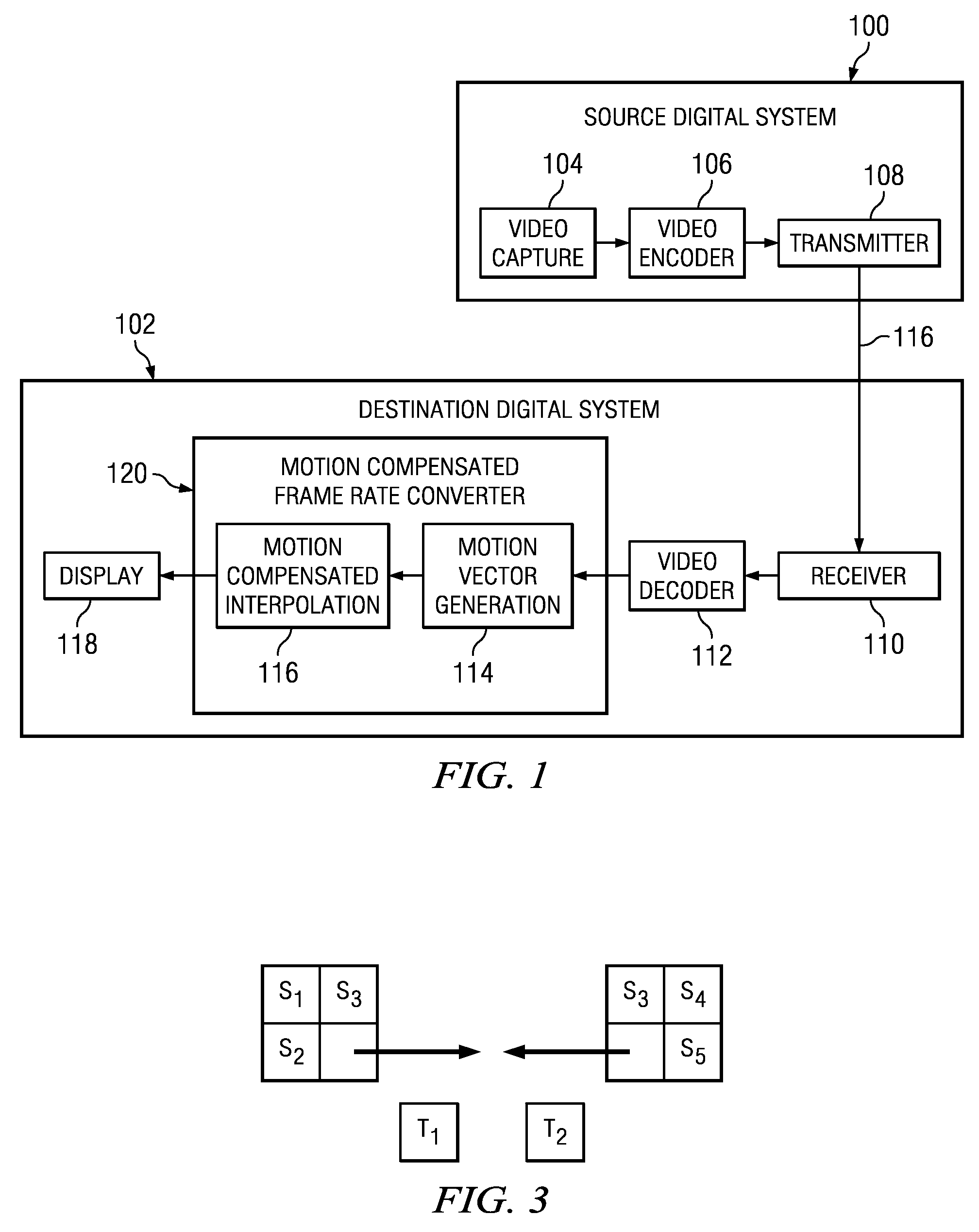
[0018]Specific embodiments of the invention will now be described in detail with reference to the accompanying figures. Like elements in the various figures are denoted by like reference numerals for consistency.

[0019]Certain terms are used throughout the following description and the claims to refer to particular system components. As one skilled in the art will appreciate, components in digital systems may be referred to by different names and / or may be combined in ways not shown herein without departing from the described functionality. This document does not intend to distinguish between components that differ in name but not function. In the following discussion and in the claims, the terms “including” and “comprising” are used in an open-ended fashion, and thus should be interpreted to mean “including, but not limited to. . . .” Also, the term “couple” and derivatives thereof are intended to mean an indirect, direct, optical, and / or wireless electrical connection. Thus, if a f...


PUM


Abstract

Methods for coherent block-based motion estimation for motion-compensated frame rate conversion of decoded video sequences are provided. In some of the disclosed methods, motion vectors are estimated for each block in a decoded frame in both raster scan order and reverse raster scan order using prediction vectors from selected spatially and temporally neighboring blocks. Further, in some of the disclosed methods, a spatial coherence constraint that detects and removes motion vector crossings is applied to the motion vectors estimated for each block in a frame to reduce halo artifacts in the up-converted video sequence. In addition, in some of the disclosed methods, post processing is performed on estimated motion vectors to improve the coherence of the motion vectors. This post-processing includes application of vector median filters to the estimated motion vectors for a frame and / or application of a sub-block motion refinement to increase the density of the motion field.

Description

BACKGROUND OF THE INVENTION[0001]The demand for digital video products continues to increase. Some examples of applications for digital video include video communication, security and surveillance, industrial automation, and entertainment. Further, video applications are becoming increasingly mobile as a result of higher computation power in handsets, advances in battery technology, and high-speed wireless connectivity. Digital video capabilities can be incorporated into a wide range of devices, including, for example, digital televisions, digital direct broadcast systems, wireless communication devices, wireless broadcast systems, personal digital assistants (PDAs), laptop or desktop computers, Internet video streaming devices, digital cameras, digital recording devices, video gaming devices, video game consoles, personal video recorders, etc.[0002]Video compression is an essential enabler for digital video products. Compression-decompression (CODEC) algorithms enable storage and t...

Claims


Application Information

Patent Timeline
Patent Type & Authority Applications(United States)
IPC IPC(8): H04N7/26
CPCH04N5/145
Inventor HONG, WEI
Owner TEXAS INSTR INC
Learn More