
Router, information processing device having said router, and packet routing method

a technology of information processing device and router, which is applied in the field of router for routing packets, information processing device having router, and packet routing method, can solve the problems of packet invalidation and processing cannot be completed in one stage, and achieve the effect of reducing the number of packets input to the network and reducing the processing time of routing

Inactive Publication Date: 2011-02-03
NEC CORP
View PDF6 Cites 27 Cited by
  • Summary
  • Abstract
  • Description
  • Claims
  • Application Information

AI Technical Summary

Benefits of technology

[0050]According to the present invention, a router is previously notified of the route of a packet, so that processing performed by the crossbar section can be brought forward, thereby reducing routing processing time.
[0051]Further, the control packet need not be transmitted for each transmission of a packet, whereby the number of packets input to a network is reduced.

Problems solved by technology

The operations of the four tasks depend on one another to some extent, so that processing cannot be completed in one stage.
If the prediction fails, the packet is invalidated before the packet reaches the next router.

Method used


Image

  • Router, information processing device having said router, and packet routing method
  • Router, information processing device having said router, and packet routing method
  • Router, information processing device having said router, and packet routing method

Examples


first exemplary embodiment

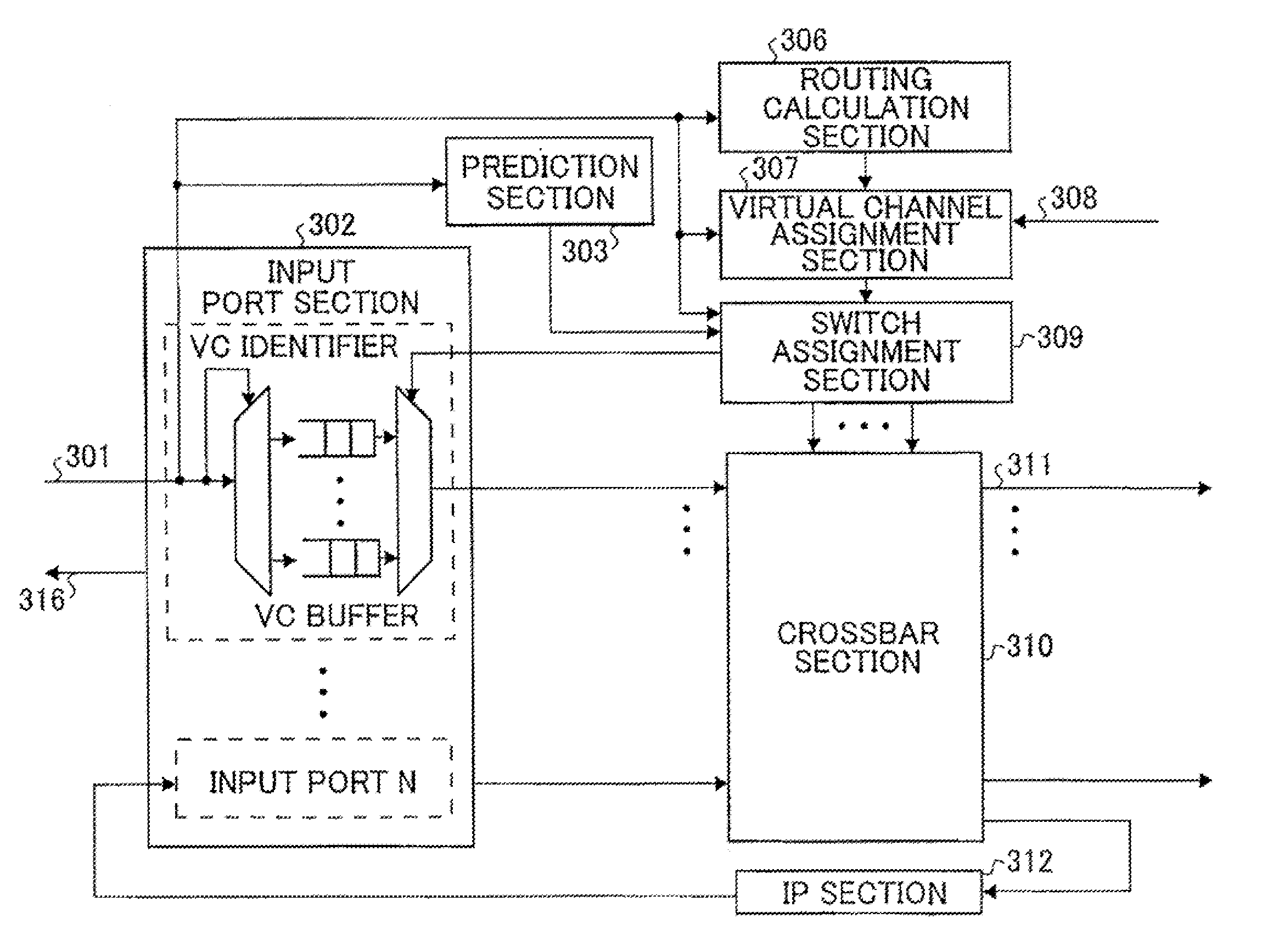
[0075]FIG. 7 is a block diagram of a router according to a first exemplary embodiment of the present invention. In FIG. 7, an IP 51 is illustrated in addition to the router. FIG. 21 is a block diagram illustrating a connection relationship between some of the blocks illustrated in FIG. 7. In FIG. 21, flit arrival time management sections 503-1 to 503-N correspond to a flit arrival time management section 503 of FIG. 7, routing calculation sections 506-1 to 506-N correspond to a routing calculation section 506 of FIG. 7, virtual channel assignment section 507-1 to 507-N correspond to a virtual channel assignment section 507 of FIG. 7.

[0076]Referring to FIG. 7, a router according to the first exemplary embodiment of the present invention has an input channel 501 that receives as an input a packet (flit) from a router as the previous hop, an input port section 502 that buffers the flit, a flit arrival time management section 503, a routing calculation section 506 that determines a rout...

second exemplary embodiment

[0147]A second exemplary embodiment of the present invention will be described in detail below with reference to the accompanying drawings. FIG. 13 is a block diagram of a router according to a second exemplary embodiment of the present invention. In FIG. 13, an IP 51 is illustrated in addition to the router. FIG. 22 is a block diagram illustrating a connection relationship between some of the blocks illustrated in FIG. 13. In FIG. 22, flit arrival time management sections 503′-1 to 503′-N correspond to a flit arrival time management section 503′ of FIG. 13, routing calculation sections 506-1 to 506-N correspond to a routing calculation section 506 of FIG. 13, virtual channel assignment section 507-1 to 507-N correspond to a virtual channel assignment section 507 of FIG. 13.

[0148]Referring to FIG. 13, a router according to the second exemplary embodiment of the present invention has an input channel 501 that receives as an input a packet (flit) from a router as the previous hop, an ...


PUM


Abstract

A router includes: a flit arrival time management section that records flit arrival time which is the time at which the packet is received for the first time, transmission interval of the packet which are acquired from a control packet transmitted prior to the first transmission of a packet and input and output channels of the control packet and requires a crossbar section for an output channel from which the packet is supposed to be output before the flit arrival time; a switch assignment section that performs arbitration on the output channel request and performs input / output connection relationship setting processing; and a switch assignment verification section that verifies whether a result of the input / output connection relationship setting processing coincides with the actual routing of the packet. The cross bar section performs switching of the arriving packet using a result of the input / output connection relationship processing.

Description

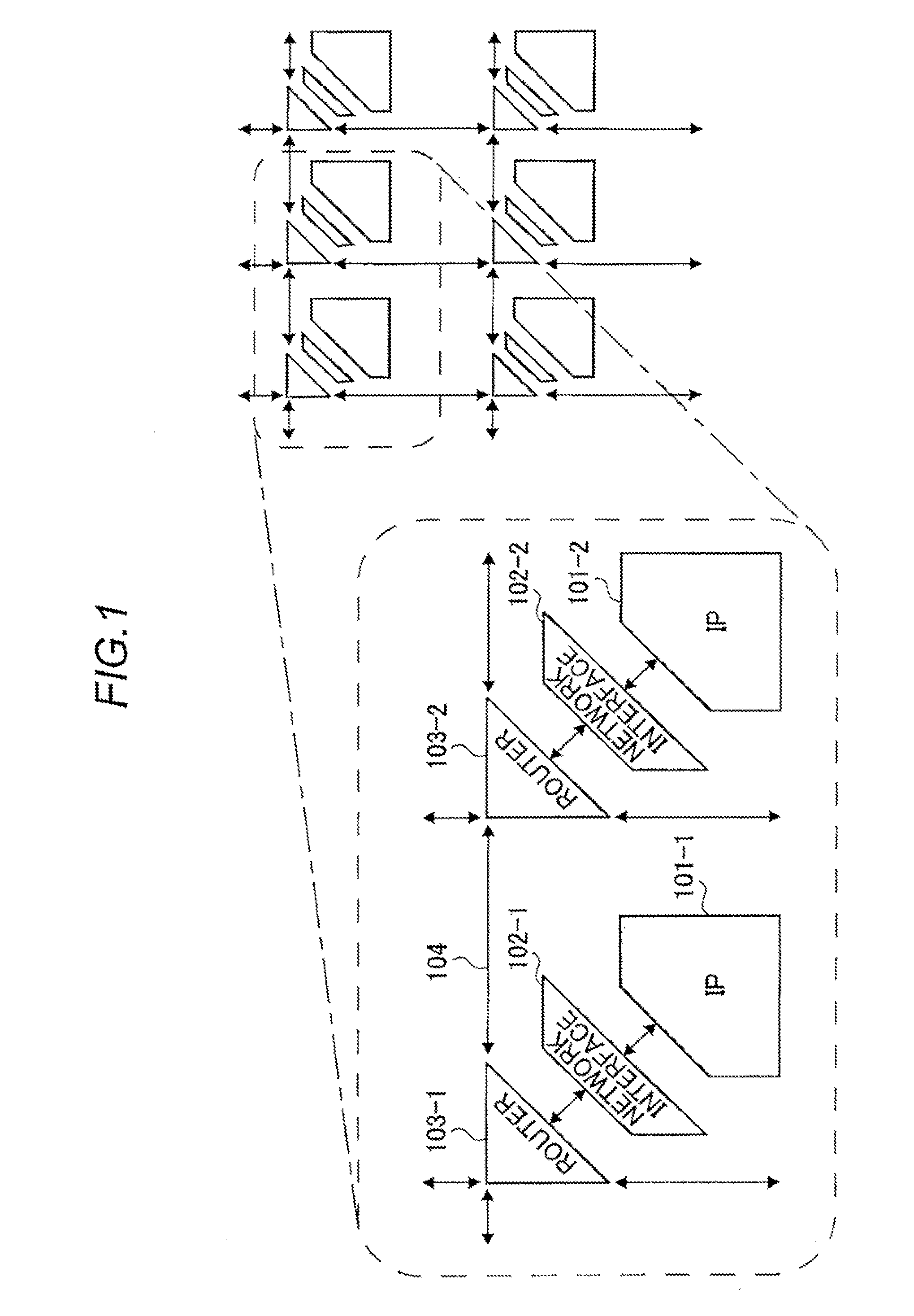
TECHNICAL FIELD [0001]The present invention relates to a router for routing a packet, an information processing device having the router, and a packet routing method.BACKGROUND ART [0002]Development in a process technology makes it possible to mount a large number of Intellectual Properties (IPs) on a single chip, thereby satisfying multi-function and high-performance demand.[0003]In such a chip, one IP needs to communicate with other many IPs and, therefore, a communication network is required. Under the circumstance, a method of connecting IPs to one another by means of point-to-point channels and routers in a structured manner is proposed, which is called Network on Chip (NoC).[0004]FIG. 1 illustrates a general configuration of an information processing device using the NoC technology. As illustrated in FIG. 1, components each including an IP, a network interface, and a router are two-dimensionally arranged. In the left part of FIG. 1, two adjacent components are illustrated in a...

Claims


Application Information

Patent Timeline
IPC IPC(8): H04L12/56H04L12/26
CPCH04L45/00H04L45/60H04L49/1546H04L49/109H04L49/251H04L45/76
Inventor TAKAGI, MASAMICHITORII, SUNAO
Owner NEC CORP
Learn More