
Alarm device

a technology of alarm device and alarm head, which is applied in the direction of fire alarm, electric transmission signalling system, instruments, etc., can solve the problems of increasing costs, preventing the security of a stable communication environment, and a chance to spread of fire or other problems

Active Publication Date: 2011-02-03
HOCHIKI CORP
View PDF9 Cites 9 Cited by
  • Summary
  • Abstract
  • Description
  • Claims
  • Application Information

AI Technical Summary

Benefits of technology

[0030]In the alarm device according to the first aspect disclosed in (1) above, an event signal for a communication test is transmitted to the other alarm devices when an alarm device test switch or the like is operated, and in response, the other alarm devices announce their reception status. By these announcements, users can ascertain the status of wireless communication between a plurality of alarm devices. If an abnormal condition is judged due to poor test results for reception status, measures can be taken such as changing the installed locations of alarm devices. As a result, when an abnormal condition such as a fire occurs, linked alarm output can be performed wirelessly by a plurality of alarm devices in a reliable manner, thereby enhancing the reliability of linked alarm output. Accordingly, the first object whereby reliable linked alarm output can be performed wirelessly between a plurality of residential alarm devices can be realized.
[0031]Furthermore, by employing a configuration in which a graphic or voice message reflecting the received signal strength is displayed or output even if the test results are judged as normal, a measure of the communication status can be easily ascertained. In this case, when the test results are only borderline normal, proactive measures can be taken such as changing the installed location of the alarm devices to achieve more reliable alarm linkage, enabling the reliability of alarm linkage to be further enhanced.
[0032]Moreover, in the alarm device according to the second aspect disclosed in (8) above, when a failure such as a low battery occurs in any of a plurality of wireless alarm devices installed in a linked manner in a residence or the like, this failure is reported to the other alarm devices and an audible failure alarm is output in a linked manner. Accordingly, when a failure occurs in an alarm device installed in an unoccupied room, the fact that a failure has occurred in an alarm device can be ascertained from the failure alarm emitted by the other alarm devices. As a result, a situation in which a failure goes unnoticed causing an alarm device to fail to operate in the event of an actual fire can be prevented. Therefore, the second object whereby a failure occurring among a plurality of alarm devices which perform linked alarm output can be reliably ascertained permitting the appropriate action to be taken, can be realized.
[0033]Furthermore, in the alarm device disclosed in (9) above, when an audible failure alarm is output by all alarm devices including the failure source, if an alarm stop operation is performed at an arbitrary alarm device, an event signal to confirm the failure source is transmitted to the other alarm devices. Thereupon, the audible failure alarm of the failure source alarm device changes to an audible announcement indicating a failure source. As a result, the alarm device where the failure occurred can be identified by straightforward and simple means, and measures such as repair can be taken.
[0034]Moreover, in the alarm device according to (10) above, when an audible failure alarm is to be output by all alarm devices including the failure source, by outputting the audible failure alarms in a preset sequence, any ambiguity that results when a plurality of alarm devices report a failure concurrently can be avoided.
[0036]Moreover, in the alarm device disclosed in (12) above, when an audible failure alarm is output by the failure representative alarm device, if an alarm stop operation is performed, an event signal for failure source confirmation is transmitted to the other alarm devices, and an audible announcement indicating the failure source is output from the failure source alarm device, enabling the alarm device where the failure occurred to be identified by straightforward and simple means, and allowing measures such as repair to be taken.

Problems solved by technology

When a plurality of alarm devices are installed in a single residence in this manner, a person who is present in a different room from the room where the abnormal condition occurred may not hear the alarm sound, giving the fire or other problem a chance to spread.
However, because providing a wired connection between alarms requires that wiring be installed, a problem arises in terms of increased costs.
However, with wireless alarm devices which enable linked alarms output, a problem exists whereby the surrounding environment has an effect on communication range, preventing a stable communication environment from being secured on an ongoing basis.
For example if wireless alarm devices are installed in each room in a residence, communication may be impeded when the door to a room is closed.
When the communication environment is adversely affected in this way, a problem may occur in that when a given alarm device detects a fire or other abnormal condition and issues an alarm, an alarm cannot be output from the other alarm devices serving as linkage destinations.
However, when an alarm device is installed in an unoccupied room, even if a low battery is detected and an audible alarm is output, there is a danger of the battery going flat if the alarm goes unnoticed by a user.

Method used


Image

  • Alarm device
  • Alarm device
  • Alarm device

Examples


first embodiment

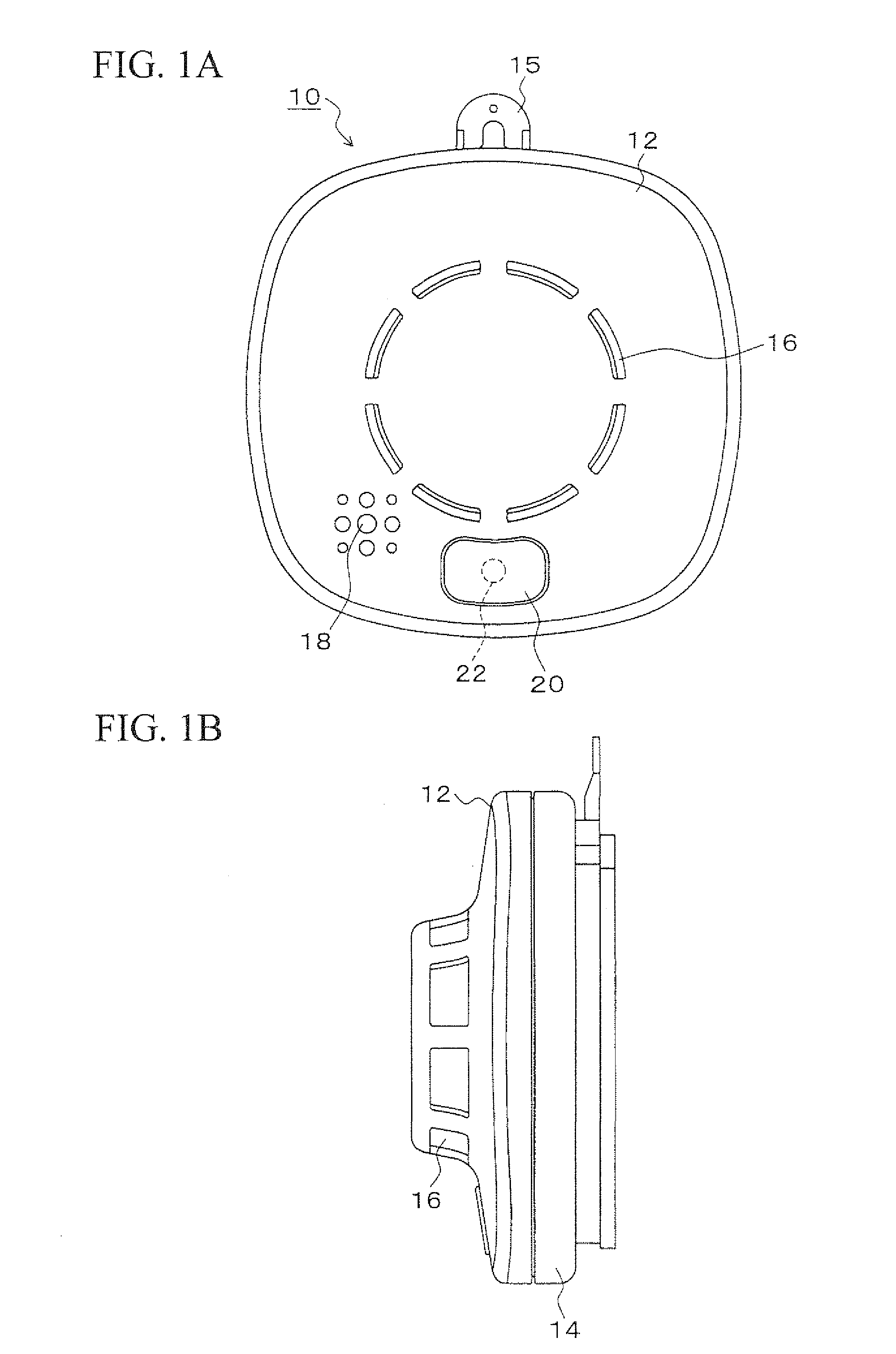
[0124]FIG. 1A and FIG. 1B are explanatory drawings showing the outward appearance of a wireless alarm device according to a first embodiment of the present invention, wherein FIG 1A is a front view and FIG. 1B a side view.

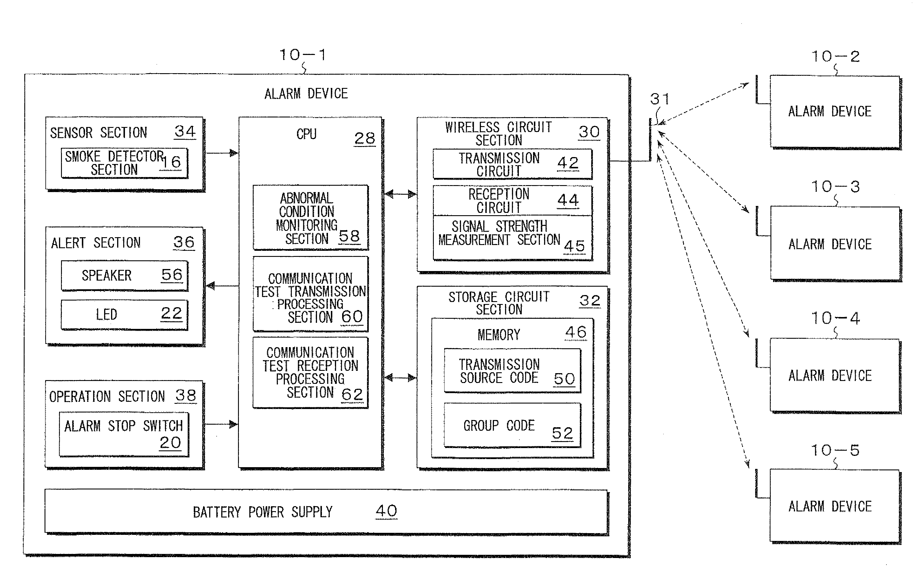
[0125]As shown in FIG. 1A and FIG. 1B, an alarm device 10 of the present embodiment comprises a cover 12 and a main unit 14. At the center of the cover 12, a smoke detector section 16, with openings through which smoke can enter formed around the periphery, is disposed, which detects a fire when smoke from the fire reaches a predetermined concentration.

[0126]At the lower left side of the smoke detector section 16, a sound hole 18 is provided. A speaker (not shown in the drawing) is housed behind this such that an audible alarm or voice message can be output. Underneath the smoke detector section 16, an alarm stop switch 20 is provided. The alarm stop switch 20 also functions as a test switch.

[0127]Inside the alarm stop switch 20, an LED 22 is installed as illustrat...

second embodiment

[0181]FIG. 8 shows an alarm device according to a second embodiment of the present invention, as a front view of an alarm device comprising a signal strength display section.

[0182]The construction of the alarm device 10 in FIG. 8 is fundamentally the same as the construction of the first embodiment, but in the present embodiment, a signal strength display section 64 is added to the right side of the cover 12. As the signal strength display section 64, a small scale LCD unit is used, which displays an antenna symbol next to a bar graph of three bars whose respective lengths indicate a weak, moderate, or strong signal strength. The display in the figure corresponds to a strong signal strength, where three bars are displayed. When the signal strength is moderate, the bar graph displays only the smaller two bars, and when the signal strength is weak only the smallest bar is displayed. In addition, in the event of abnormal communication, the bar graph display disappears, leaving only the...

third embodiment

[0189]FIG. 9A and FIG. 9B are explanatory drawings showing the outward appearance of a wireless alarm device according to a third embodiment of the present invention, wherein FIG. 9A is a front view and FIG. 9B a side view.

[0190]As shown in FIG. 9A and FIG. 9B, an alarm device 110 of the present embodiment comprises a cover 112 and a main unit 114. At the center of the cover 112, a smoke detector section 116, with openings through which smoke can enter formed around the periphery, is disposed, which detects a fire when smoke from the fire reaches a predetermined concentration.

[0191]At the lower left side of the smoke detector section 116 provided in the cover 112, a sound hole 118 is provided. A speaker (not shown in the drawing) is housed behind this such that an audible alarm or voice message can be output. Underneath the smoke detector section 116, an alarm stop switch 120 is provided. The alarm stop switch 120 also functions as a test switch.

[0192]Inside the alarm stop switch 12...


PUM


Abstract

An alarm device includes: a wireless circuit section which wirelessly exchanges event signals with an other alarm device; an alert section which outputs an alarm; an operation section which accepts predetermined operations; a sensor section which issues an abnormal condition detection signal when an abnormal condition occurred is detected within a monitoring area; an abnormal condition monitoring section which, upon receiving the abnormal condition detection signal from the sensor section, outputs an abnormal condition alarm as a linkage source from the alert section, and transmits an event signal indicating an abnormal condition to the other alarm devices, and conversely, upon receiving an event signal indicating an abnormal condition from the other alarm device, outputs an abnormal condition alarm as a linkage destination from the alert section; a communication test transmission processing section which, at a predetermined timing, transmits an event signal indicating a communication test to the other alarm device and; a communication test reception processing section which, upon receiving an event signal indicating a communication test from the other alarm device, announces the reception status of this event signal.

Description

BACKGROUND OF THE INVENTION[0001]1. Field of the Invention[0002]The present invention relates to an alarm device which detects an abnormal condition such as a fire and emits an alarm, and also wirelessly transmits a signal to other alarm devices to facilitate linked alarm output.[0003]Priority is claimed on Japanese Patent Application No. 2008-075037, and Japanese Patent Application No. 2008-075119, the contents of which are incorporated herein by reference.[0004]2. Description of Related Art[0005]Conventionally, household alarm devices (hereafter “alarm devices”) which detect abnormal conditions such as fires or gas leaks in a residence and issue an alarm have become prevalent, and in recent years there is a proposal for ones that monitor for abnormal conditions such as a fire on a room-by-room basis by installing a plurality of alarm devices throughout a single residence (refer to Japanese Unexamined Patent Application, First Publication No. 2007-094719, for example).[0006]When a ...

Claims


Application Information

Patent Timeline
IPC IPC(8): G08B29/00
CPCG08B17/00G08B25/009G08B29/181G08B7/06G08B29/123G08B17/113
Inventor EGAWA, YOSHITAKAMATSUKUMA, HIDENARI
Owner HOCHIKI CORP
Learn More