
Direct current steam plasma torch and method for reducing the erosion of electrodes thereof

a technology of direct current and steam plasma torch, which is applied in the direction of plasma welding apparatus, gas-filled discharge tubes, manufacturing tools, etc., can solve problems such as hazardous byproducts, and achieve the effect of stabilizing the properties of operation and reducing the erosion of first and second electrodes

Inactive Publication Date: 2011-02-03
INST NUCLEAR ENERGY RES ROCAEC
View PDF7 Cites 13 Cited by
  • Summary
  • Abstract
  • Description
  • Claims
  • Application Information

AI Technical Summary

Benefits of technology

[0009]It is another objective of the present invention to provide a method for reducing the erosion of first and second electrodes of a DC steam plasma torch.
[0010]To achieve the foregoing objective, a negative high-voltage terminal of a DC power supply is connected to a helical coil via a conducting element. Another terminal of the DC power supply is connected to the first electrode. There is provided first coaxial thermostatic piping including a first swirl generator to introduce primary working gas into the first and second electrodes. There is provided a trigger generator to generate a discharge arc between the first and second electrodes. The current and the flow rate of the primary working gas are gradually increased to cause an arc root to enter the internal side of the first and second electrodes to generate a high-speed swirl on the internal side of the first and second electrodes. There is provided second thermostatic piping including a second swirl generator to introduce auxiliary working gas into the second electrode periodically to regulate the pressure in the rear electrode to move the arc root to and fro axially. There is provided an inlet conduit to introduce pulsed and pressurized air into the second electrode to clean the internal side of the second electrode of residual powder to retain the normal distribution of a current filed in the second electrode to stabilize the properties of the operation of the DC steam plasma torch.

Problems solved by technology

Where air and nitrogen are used, there may be hazardous byproducts such as NOX.

Method used


Image

  • Direct current steam plasma torch and method for reducing the erosion of electrodes thereof
  • Direct current steam plasma torch and method for reducing the erosion of electrodes thereof
  • Direct current steam plasma torch and method for reducing the erosion of electrodes thereof

Examples


Embodiment Construction

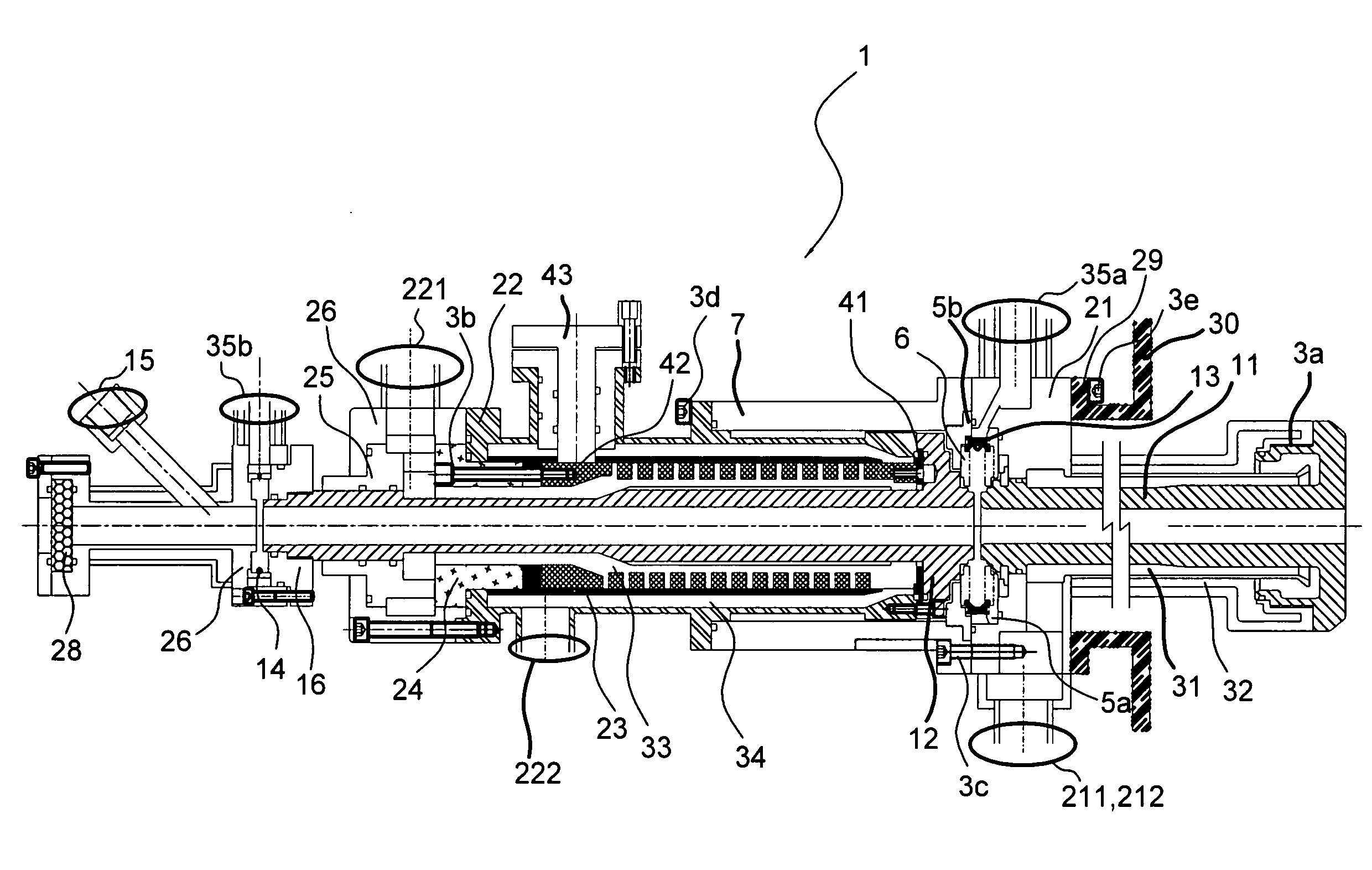
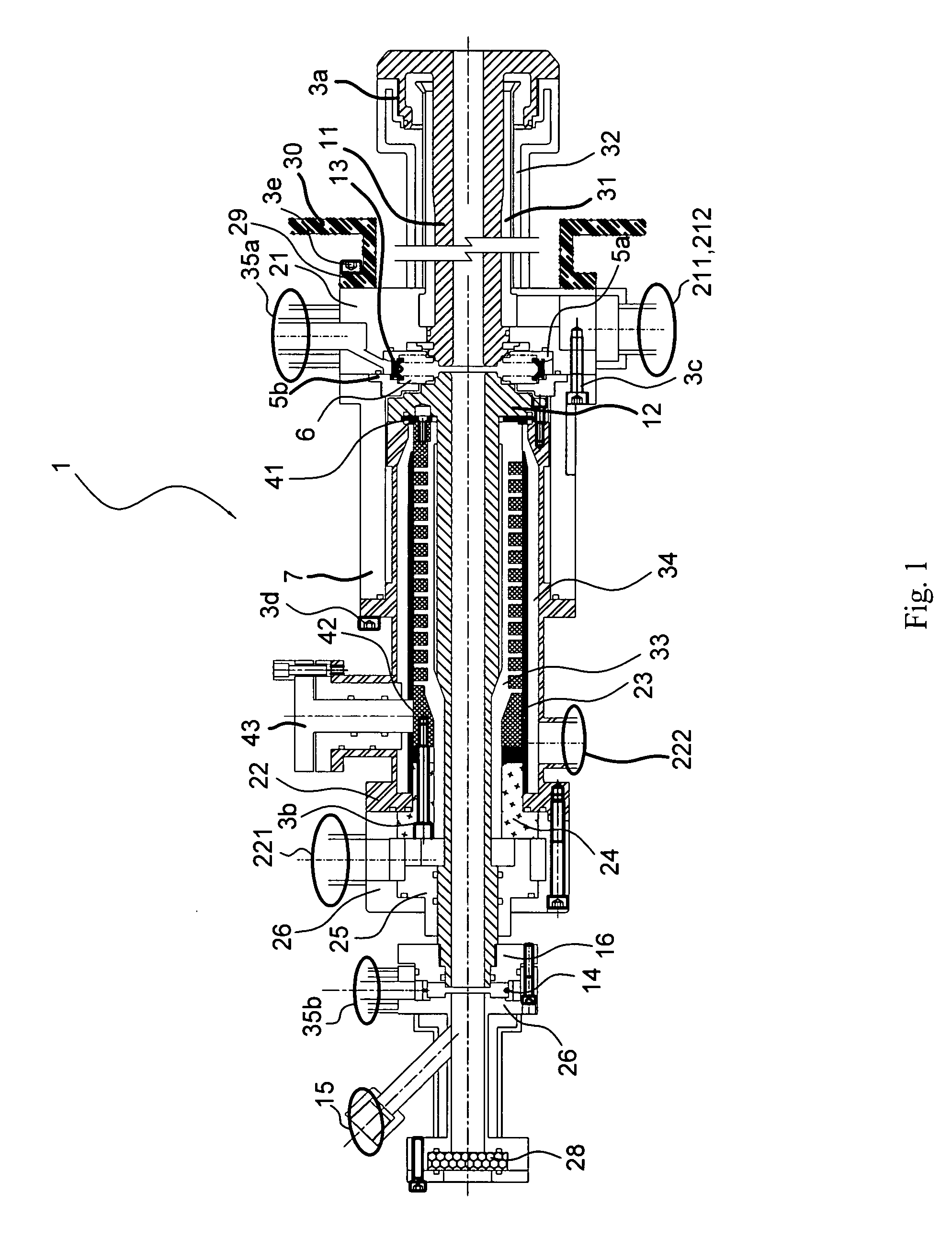
[0017]Referring to FIG. 1, a DC steam plasma torch 1 includes a front section, a middle section and a rear section according to the preferred embodiment of the present invention. There is a first swirl (or “vortex”) generator 13 between the front and middle sections. There is a second swirl generator 14 between the middle and rear sections.

[0018]The front section of the DC steam plasma torch 1 includes a first electrode 11 and a first mount 21. Both of the first electrode 11 and the first mount 21 are tubular. With a threaded bolt 3a, the first electrode 11 is co-axially connected to the first mount 21, thus defining a first internal channel 31 and a first external channel 32. Coolant can travel in the first internal channel 31 and the first external channel 32.

[0019]The middle section of the DC steam plasma torch 1 includes a second electrode 12 and a second mount 22. Both of the second electrode 12 and the second mount 22 are tubular. The second electrode 12 is co-axially connecte...


PUM

PropertyMeasurementUnit
temperatureaaaaaaaaaa
conductiveaaaaaaaaaa
insulatingaaaaaaaaaa

Abstract

A DC steam plasma torch includes front, middle and rear sections. The front section includes a first amount and a first electrode attached to the first amount, thus defining co-axial first internal and external coolant channels. The middle section includes a second mount and a second electrode co-axially connected to the second mount, thus defining co-axial second internal and external coolant channels. The rear section includes an insulating transient element connected to the second electrode, a window frame connected to the insulating transient element and a window provided in the window frame. A first swirl generator is provided between the first and second sections to receive primary working gas and generating a swirl in the same. A second swirl generator is provided between the middle and rear sections to receive auxiliary working gas and generating a swirl in the same.

Description

BACKGROUND OF INVENTION[0001]1. FIELD OF INVENTION[0002]The present invention relates to a direct current (“DC”) steam plasma torch and a method for reducing the erosion of electrodes thereof.[0003]2. RELATED PRIOR ART[0004]Plasma torches have been widely used in the metallurgy of special metal, the making of extremely fine particles and the changing of superficial properties. In the protection of the environment, plasma torches have been used to melt, pyrolyze or gasify flammable or non-flammable toxic waste, lowly radioactive waste, ash from incinerators or perfluorocompounds for de-toxication, volume reduction, solidification or conversion into resources.[0005]As disclosed in U.S. Pat. Nos. 4,587,397 and 4,625,092 issued on 6 May 1986, working gas is only introduced into a DC plasma torch between front and rear electrodes of the DC plasma torch, and the rear electrode is a closed-loop gas supply system. A magnetic field may or may not be provided in the DC plasma torch. Where no ...

Claims


Application Information

Patent Timeline
Patent Type & Authority Applications(United States)
IPC IPC(8): B23K10/00
CPCH05H1/3405
Inventor LIN, DENG-LIANTZENG, CHIN-CHING
Owner INST NUCLEAR ENERGY RES ROCAEC
Learn More