
Drainage trapping cartridge and a drainage trapping device for preventing backflow of gas

a technology of drainage trapping and cartridge, which is applied in the direction of water installation, construction, domestic plumbing, etc., can solve the problems of indoor air and living environment, harm to personal health, and feeling bad

Inactive Publication Date: 2011-02-03
MICRO TECH DEV
View PDF5 Cites 4 Cited by
  • Summary
  • Abstract
  • Description
  • Claims
  • Application Information

AI Technical Summary

Benefits of technology

In accordance with some embodiments of the present invention, a drainage trapping device for preventing backflow of gas and a drainage trapping cartridge are provided, which can provide a solution to backflow of gas occurring in the conventional drainage trapping device.
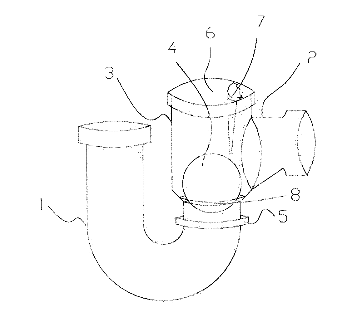
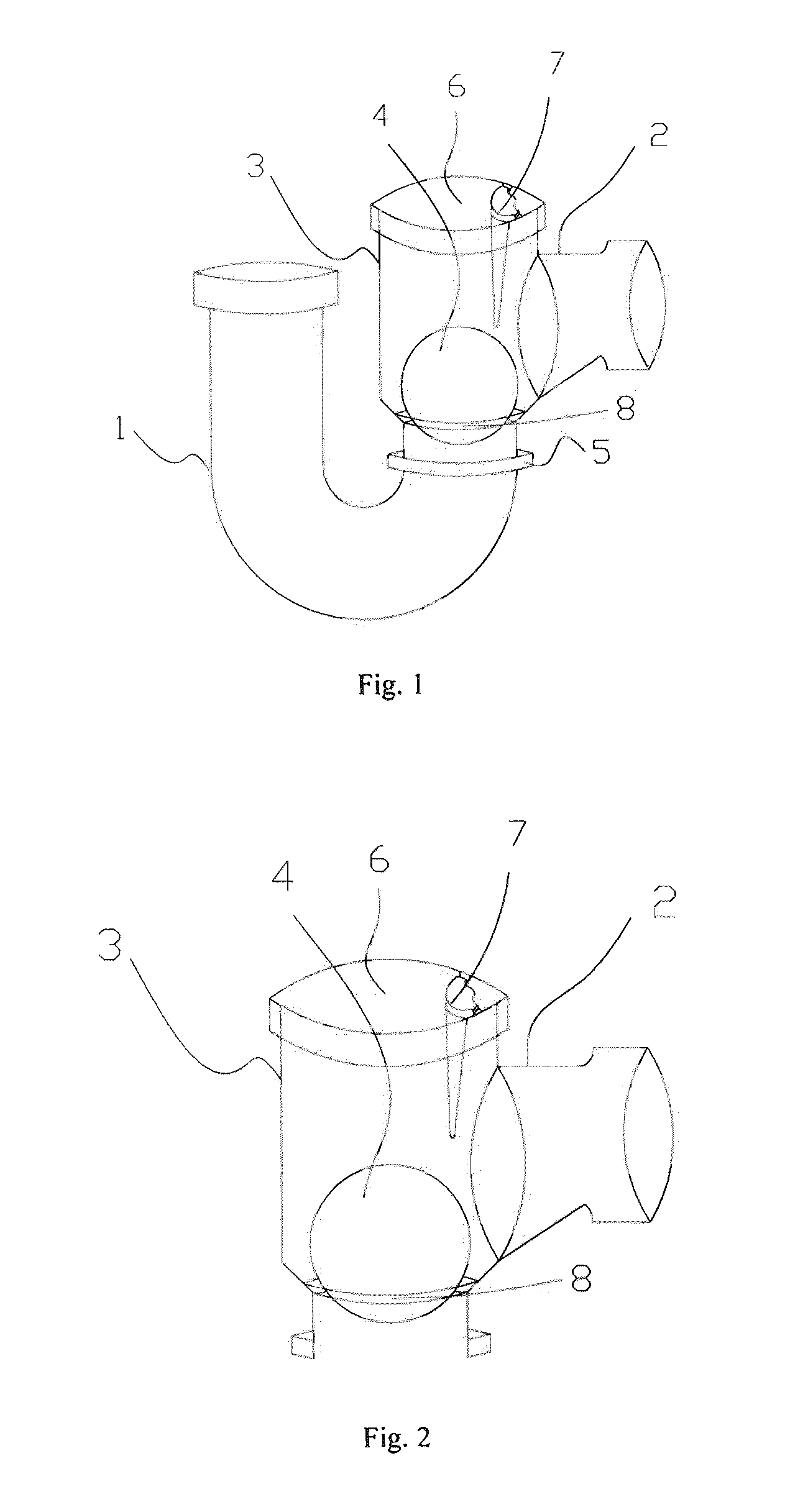
A drainage trapping cartridge comprises a water inlet, a water outlet, a float valve disposed inside the drainage trapping cartridge, a retaining component disposed at the water outlet of the drainage trapping cartridge. The float valve is configured for hermetically engaging with a lower part of the drainage trapping cartridge when the drainage trapping cartridge is devoid of water. The float valve defines a diameter higher than that of the lower part of the drainage trapping cartridge. The retaining component is configured for preventing the float valve from running out. The retaining component is a block-shaped or rod-shaped component radially projected from inner circumference of the water outlet of the drainage trapping cartridge or is an integral form of an annular component engaged to the drainage trapping cartridge and a block-shaped or rod-shaped component projected from inner circumference of the annular component.
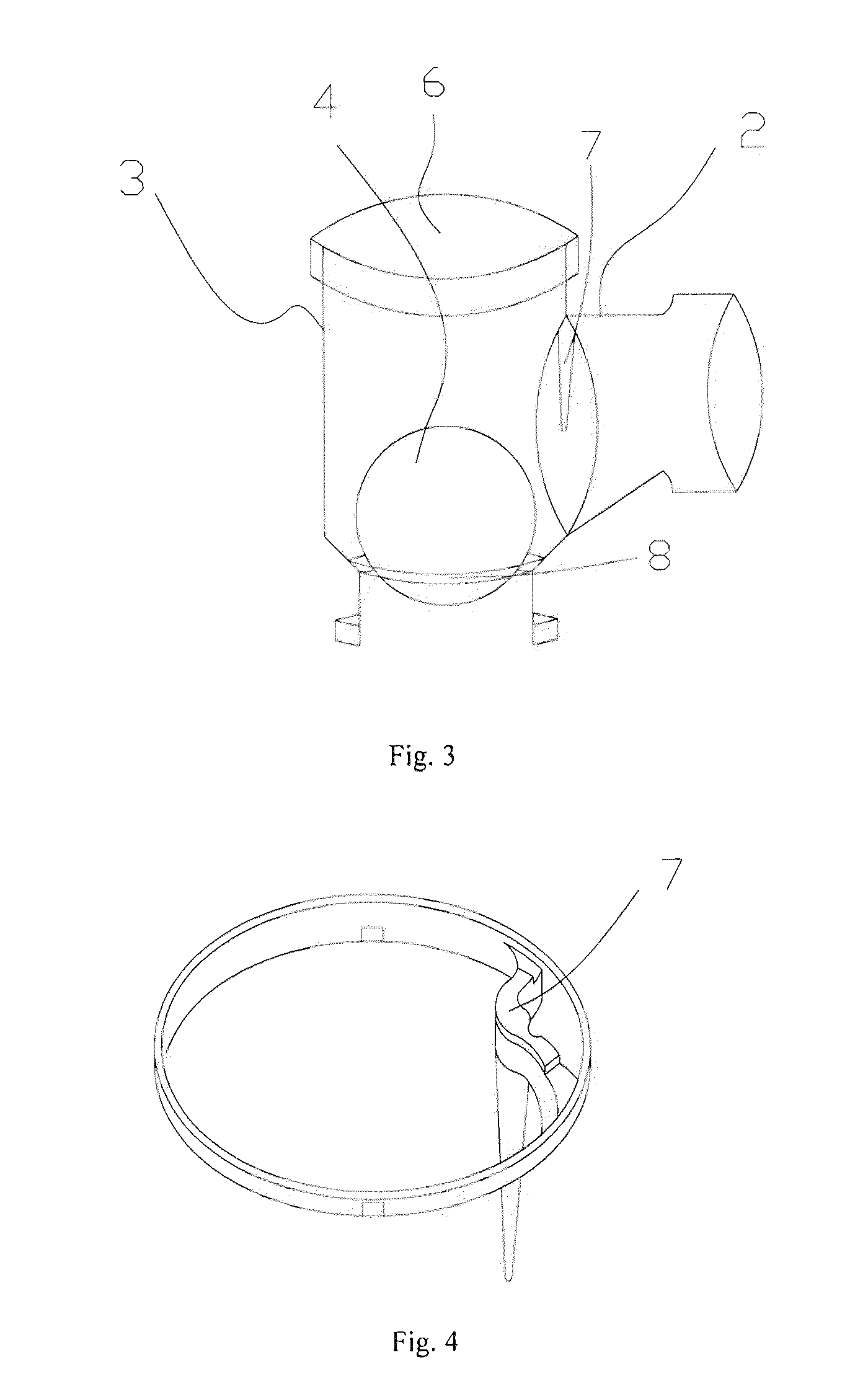
In the present invention, the float valve floats on the water during water draining so that the water can smoothly pass through the drainage trapping cartridge and the water outlet pipe, and enter the outdoor main sewage drainage pipe. When the water is not drained, the water accumulated at the bottom of the drainage trapping device can prevent the gas from flowing backwards to the interior of the building from the outside. When the water in the drainage trapping device is continuously vaporized till dries up completely, the float valve can close and seal up the bottom of the drainage trapping cartridge due to its gravity and its diameter higher than that of the bottom of the drainage trapping cartridge. In this way, the float valve can prevent the waste gas or poisonous gas containing bacteria from flowing backwards into the interior of the building. In the event that the gas flows backwards, the float valve can more tightly seal up the bottom of the drainage trapping cartridge under higher gas pressure. The drainage trapping device has a compact structure and a double protection from backflow of gas. The retaining component (e.g., a tapered rod) is disposed at the water outlet of the drainage trapping cartridge or in the water outlet pipe, for preventing the float valve from running out, which can prevent the float valve from running out without affecting the flow rate of water output and blocking the waste materials.

Problems solved by technology

As a result, people will perceive smell of the waste gas from the opening of the draining device and may feel bad if inhaling the waste gas.
However, if the accumulated water at the U-type lower bottom of the drainage trapping device is subject to siphon absorption or evaporated due to heat, the waste gas or poisonous gas containing bacteria at the water outlet will easily enter the interior of the building and thus pollute the indoor air and living environment, thereby forming harm to personal health.

Method used


Image

  • Drainage trapping cartridge and a drainage trapping device for preventing backflow of gas
  • Drainage trapping cartridge and a drainage trapping device for preventing backflow of gas
  • Drainage trapping cartridge and a drainage trapping device for preventing backflow of gas

Examples


Embodiment Construction

Objects, advantages and embodiments of the present invention will be explained below in detail with reference to the accompanying drawings. However, it is to be appreciated that the following description of the embodiment(s) is merely exemplary in nature and is no way intended to limit the invention, its application, or uses.

Referring to FIGS. 1, 2 and 3, FIG. 1 shows a drainage trapping device, also referred to as a drainage gas-shielding device, for preventing backflow of gas in accordance with an embodiment of the present invention. The drainage trapping device is in a U-shaped form and includes a water inlet pipe 1, a water outlet pipe 2, a drainage trapping cartridge 3 and a float valve 4. The float valve 4 is configured (i.e., structured, arranged or adapted) for hermetically engaging with a lower part of the drainage trapping (i.e., gas-shielding) cartridge when the drainage trapping cartridge is devoid of water.

The water inlet pipe 1 is connected with the drainage trapping c...


PUM


Abstract

The present invention provides a drainage trapping device which can prevent waste gas or poisonous gas containing bacteria from flowing backwards. The drainage trapping device comprises a water inlet pipe, a drainage trapping cartridge, a water outlet pipe, a float valve and a retaining component. The drainage trapping cartridge is provided with a water outlet which is connected to the water outlet pipe. A lower end of the drainage trapping cartridge is connected with the water inlet pipe. The float valve is disposed inside the drainage trapping cartridge and hermetically engages with a lower part of the drainage trapping cartridge when the drainage trapping cartridge is devoid of water. The retaining component is disposed at the water outlet of the drainage trapping cartridge or in the water outlet pipe, for preventing the float valve from running out.

Description

FIELDThe present invention relates to drainage trapping devices and, more particularly a drainage trapping device cartridge and a drainage trapping device, which can prevent the waste gas or poisonous gas containing bacteria from flowing backwards.BACKGROUNDNowadays, people have paid more and more attention to the details of living environment, such as the installation of furnishings, scientific design of living facilities etc. For the storied buildings where people live, the drainage trapping devices, also referred to as drainage gas-shielding devices, are absolutely necessary in daily life because they control the draining of domestic water etc. The gas may flow backwards if there is no suitable trapping device in the drainage pipe. As a result, people will perceive smell of the waste gas from the opening of the draining device and may feel bad if inhaling the waste gas.At present, the drainage trapping device for preventing the gas from flowing backwards is U-shaped. Due to U-sha...

Claims


Application Information

Patent Timeline
Patent Type & Authority Applications(United States)
IPC IPC(8): E03C1/12
CPCE03C1/288
Inventor TONG, YIU KWOKLAM, KWAI HUNG
Owner MICRO TECH DEV
Learn More