Power Supply Auxiliary Circuit

a technology of auxiliary circuit and power supply, which is applied in the direction of ac-dc conversion without reversal, power conversion system, electrical apparatus, etc., can solve the problem of relatively longer usable life of the auxiliary circuit of the power supply, and achieve the effect of longer usable li

Inactive Publication Date: 2011-01-27
WELL SHIN TECH
View PDF3 Cites 4 Cited by
  • Summary
  • Abstract
  • Description
  • Claims
  • Application Information

AI Technical Summary

Benefits of technology

[0006]An object of the present invention is to provide a power supply auxiliary circuit which includes a power input unit for receiving an AC input voltage from an external power supply, a voltage regulating unit for dropping the AC input voltage from the power input unit, a rectifying unit for converting the dropped AC input voltage by the voltage regulating unit into a DC voltage, a snubber unit for filtering the DC voltage into a proper DC output voltage, a power output unit for supplying the proper DC output voltage filtered by the snubber unit to an external circuit, a switch unit connected between the rectifying unit and a feedback control unit, and the feedback control unit connected between the power output unit, and the switch unit for detecting and analyzing the output voltage of the power output unit and then generating a corresponding control signal so as to determine a switch state of the switch unit that makes the current from the rectifying unit partially back-flow to the power input unit or not, and further regulates the value of the output voltage of the power output unit. Therefore, the power supply auxiliary circuit of the present invention can always supply a relatively constant DC output voltage to the external circuit. Furthermore, even if the external circuit is unexpectedly disconnected from the power output unit, a high-powered current can be avoided to generate thereby so that the power supply auxiliary circuit has a relatively longer usable life.

Problems solved by technology

Furthermore, even if the external circuit is unexpectedly disconnected from the power output unit, a high-powered current can be avoided to generate thereby so that the power supply auxiliary circuit has a relatively longer usable life.

Method used


Image

  • Power Supply Auxiliary Circuit
  • Power Supply Auxiliary Circuit
  • Power Supply Auxiliary Circuit

Examples


Embodiment Construction

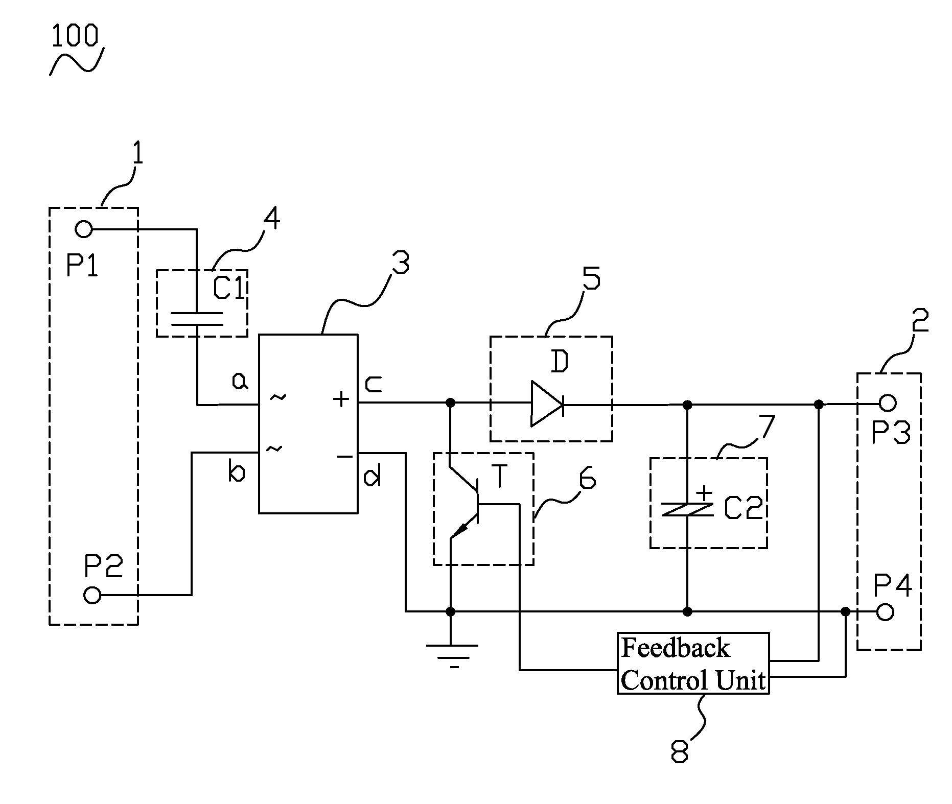
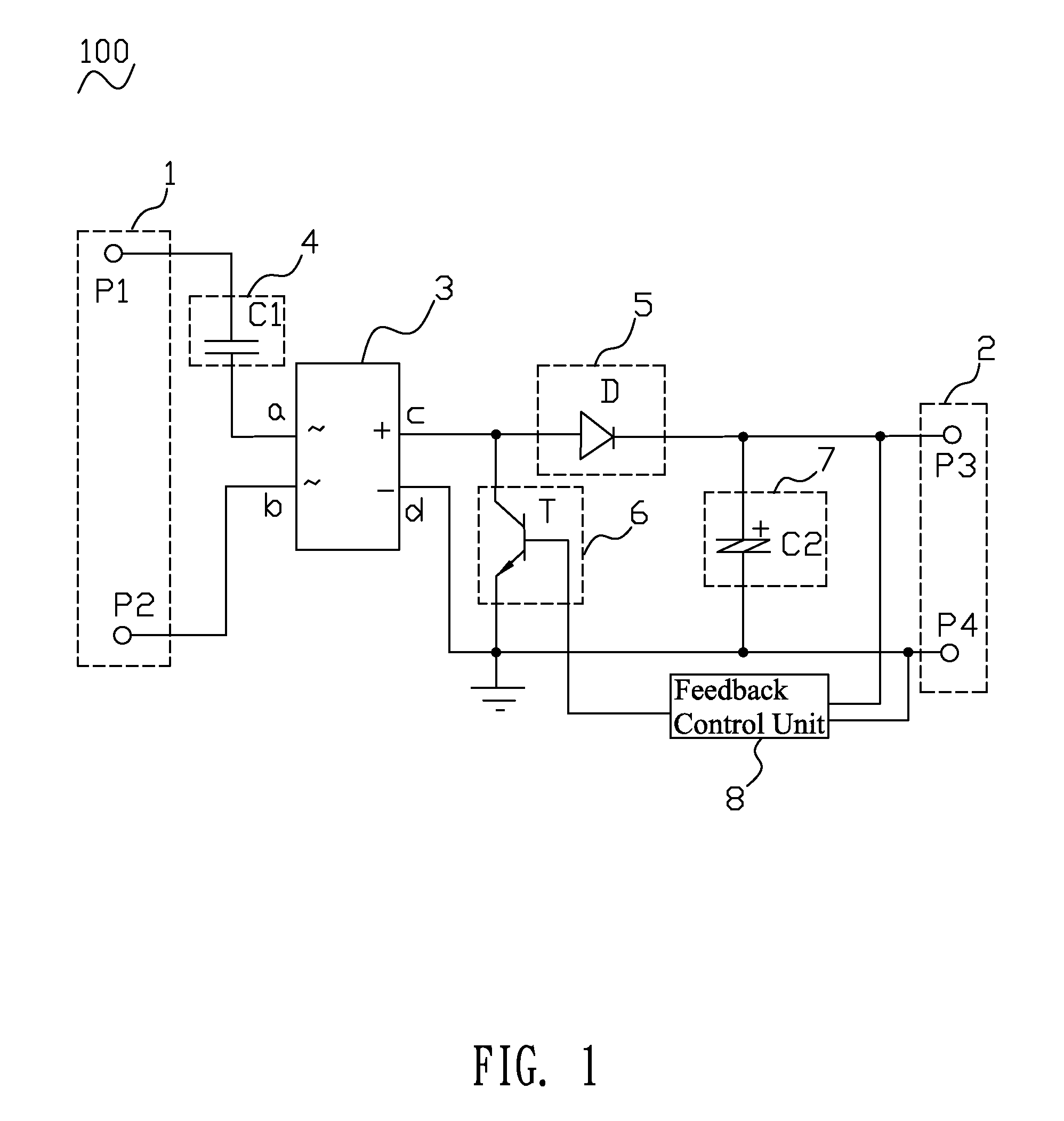
[0010]With reference to FIG. 1, a power supply auxiliary circuit 100 of the prevent invention includes a power input unit 1, a power output unit 2, a rectifying unit 3, a voltage regulating unit 4, an unidirectional unit 5, a switch unit 6, a snubber unit 7 and a feedback control unit 8.

[0011]The power input unit 1 includes a live input terminal P1 and a neutral input terminal P2 and is adapted for connecting an external AC power supply (not shown) to get an AC input voltage. The power output unit 2 includes a positive output terminal P3 and a negative output terminal P4 and is adapted for connecting an external circuit (not shown) to supply a required DC output voltage thereto.

[0012]The rectifying unit 3 may be either a full-wave rectifier or a half-wave rectifier and is adapted for converting AC into DC. The rectifying unit 3 has a first connecting terminal a, a second connecting terminal b, a positive connecting terminal c and a negative connecting terminal d. The voltage regulat...


PUM


Abstract

A power supply auxiliary circuit includes a power input unit for receiving an AC input voltage, a voltage regulating unit for dropping the AC input voltage, a rectifying unit for converting the dropped AC input voltage into a DC voltage, a snubber unit for filtering the DC voltage, a power output unit for sending the filtered DC voltage, a switch unit connected between the rectifying unit and a feedback control unit, and the feedback control unit connected between the power output unit and the switch unit for detecting and analyzing the output voltage of the power output unit, and then generating a corresponding control signal to determine a switch state of the switch unit that makes the current from the rectifying unit partially back-flow to the power input unit or not, and further regulates the value of the output voltage of the power output unit.

Description

BACKGROUND OF THE INVENTION[0001]1. Field of the Invention[0002]The present invention generally relates to a power supply circuit, and more particularly to a power supply auxiliary circuit.[0003]2. The Related Art[0004]Referring to FIG. 2, a conventional power supply auxiliary circuit includes a power input unit 10, a power output unit 11, two step-down capacitors C1, C3 and a second diode D2 series-connected between the two step-down capacitors C1, C3. The power input unit 10 is drawn forth from another two terminals of the two step-down capacitors C1, C3. The power supply auxiliary circuit further includes a first diode D1 and a snubber capacitor C2 series-connected with each other and then parallel-connected to the second diode D2, wherein the first diode D1 is reverse with the second diode D2. The power output unit 11 is drawn forth from two terminals of the snubber capacitor C2 and adapted for connecting external circuits (not shown) to supply required power thereto. An input v...

Claims


Application Information

Patent Timeline
Patent Type & Authority Applications(United States)
IPC IPC(8): H02M7/06
CPCH02M7/217H02M7/06H02M7/05
Inventor KO, TI-HUA
Owner WELL SHIN TECH
Why Eureka
Try Eureka