
Rotary oil feedthrough

a technology of rotary oil and feedthrough, which is applied in the direction of engine seals, adjustable joints, pipes/joints/fittings, etc., can solve the problems of large quantity of cooling oil, significant impairment of the actual function of the seal arrangement, and significant temperature increase on the friction surface or the sealing surface of the sealing ring. , to achieve the effect of reducing the possibility of leakage, simple structural design and good response characteristics

Active Publication Date: 2011-01-27
GAPI TECHN PROD
View PDF7 Cites 4 Cited by
  • Summary
  • Abstract
  • Description
  • Claims
  • Application Information

AI Technical Summary

Benefits of technology

"The invention is a rotary oil feedthrough that has a long service life, minimal leakage, and good response characteristics. It is designed to seal off the pressurized oil compartment in the axial direction of the shaft or mount, and it can be easily assembled and adapted to different requirements. The sealing ring carrier and adapter are fastened on the shaft or mount in non-rotating fashion, and they are connected in fluid-tight fashion to prevent leakage. The sealing rings are located between the sealing ring carrier and the adapter and can be positioned axially and laterally. The sealing rings can be fixed in place on the components using a press fit or radial pressure. The invention provides a simple and robust design that reduces wear and frictional losses."

Problems solved by technology

Up to now, rectangular rings made of steel or plastic have mostly been used as the sealing rings on rotary oil feedthroughs of this kind, since the otherwise customary lip seals cannot be considered because of the high operating temperatures.
At the high rpm speeds to which shafts used with rotary oil feedthroughs of this kind are usually exposed, this results in substantial frictional forces on the sealing ring, which lead to substantial temperature increases on the friction surface or the sealing surface of the sealing ring.
However, at very high oil pressures—and thus high contact pressures of the sealing ring on the sealing surface of the respective component—and high relative speeds, the result of this is that a relatively large quantity of cooling oil is needed as the leakage flow, meaning that the actual function of the seal arrangement is significantly impaired.
Since a large number of rotary oil feedthroughs may be present in a machine, such as a transmission, the overall frictional losses of the individual rotary oil feedthroughs also lead to significant performance losses of the respective machine, such as a motor with transmission.
As a result, it is often necessary to use hardened materials in the region of the sealing surfaces.
Furthermore, the grooves, against the groove flanks of which the sealing ring can be positioned in sealing fashion, usually have to be of relatively small design, in which context it is usually difficult to gain access to the groove flanks, meaning that their machining is then also complicated.
It is then generally also difficult to check the quality of manufacture of the sealing surfaces.
This is only possible within limits on conventional rotary oil feedthroughs.

Method used


Image

  • Rotary oil feedthrough
  • Rotary oil feedthrough
  • Rotary oil feedthrough

Examples


Embodiment Construction

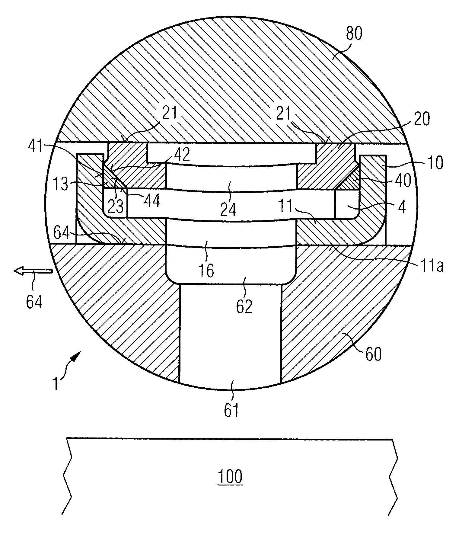
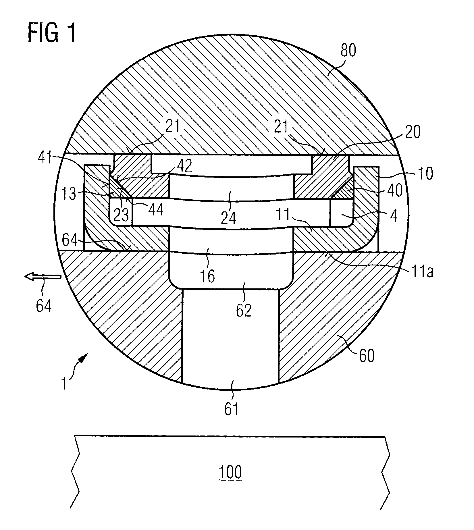
A rotary oil feedthrough 1 according to an embodiment of the invention can be used in a machine or device, such as transmission 100. The rotary oil feedthrough can be located between a rotatable shaft 60 and a shaft mount 80, where the oil-pressurizable pressure compartment 4 of the rotary oil feedthrough is connected in fluid-permeable fashion to an oil duct located in the shaft and / or the mount. According to the practical example, shaft 60 displays an oil duct 61 or an oil bore that can merge into a preferably circumferential oil groove 62 of the shaft. The rotary oil feedthrough seals off pressure compartment 4, pressurizable by oil pressure, on both sides in the axial direction of the shaft.

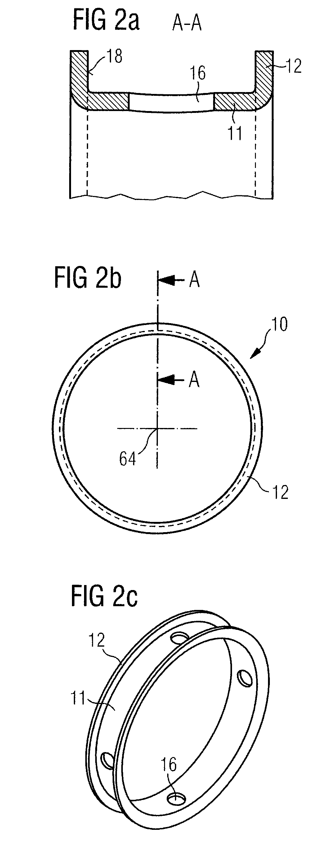
The rotary oil feedthrough according to the invention displays a sealing ring carrier 10, an adapter 20, and two sealing rings 40 that are located between sealing ring carrier 10 and adapter 20 and axially separated from each other. Sealing ring carrier 10 is located on the shaft in non-rotat...


PUM


Abstract

A rotary oil feedthrough is provided for sealing off a pressurized oil compartment between a rotatable shaft and a shaft mount, where the rotary oil feedthrough displays a radial oil passage for connecting an oil duct of the shaft and / or the mount to the pressurized oil compartment in fluid-permeable fashion, and has a seal arrangement that seals off the pressurized oil compartment on both sides in the axial direction of the shaft. The rotary oil feedthrough displays a sealing ring carrier that can be fastened to the shaft or the mount in non-rotating and fluid-tight fashion, the sealing ring carrier being arranged coaxially to the shaft or the mount, and an adapter that can be positioned on the other component of shaft and mount in fluid-tight fashion, and is surrounded laterally by the sealing ring carrier in the axial direction of the shaft. Located between sealing ring carrier and adapter are two axially separated sealing rings that each lie on the sealing ring carrier and the adapter in sealing fashion in order to seal off the pressurized oil compartment in the axial direction of the shaft, and that can be rotated relative to the sealing ring carrier and / or the adapter. The rotary oil feedthrough displays the longest possible service life, the minimum possible leakage, and good response characteristics, and is of simple structural design.

Description

BACKGROUND OF THE INVENTIONThe invention relates to a rotary oil feedthrough for sealing off a pressurized oil compartment between a rotatable shaft and a shaft mount, where the rotary oil feedthrough displays a radial oil passage for connecting an oil duct of the shaft and / or the mount to the pressurized oil compartment in fluid-permeable fashion, and has a seal arrangement that seals off the pressurized oil compartment on both sides in the axial direction of the shaft.Generic rotary oil feedthroughs are put to diverse uses, mainly in applications involving a rotary hollow shaft whose cavity forms an oil duct. In this context, the space between the shaft and the mount assigned to it is filled with oil that is usually pressurized. Where appropriate, the mount surrounding the shaft can in turn be connected to the oil-containing pressurized compartment between the shaft and the mount in fluid-permeable fashion, and the mount itself can generally be designed as a hollow shaft. The oil ...

Claims


Application Information

Patent Timeline
Patent Type & Authority Applications(United States)
IPC IPC(8): F16J15/16
CPCF16L27/087F16J15/40F16J15/34
Inventor MELLER, DIETER
Owner GAPI TECHN PROD
Learn More