Pneumatic radial tire for heavy load

a radial tire and pneumatic technology, applied in the direction of non-skid devices, vehicle components, transportation and packaging, etc., can solve the problems of reducing the amount of rubber of the generating cracks at the groove bottom, and deteriorating wear resistance at the tread surface of the land portion. , to achieve the effect of reducing a bending angle, reducing the slippage of the trailing edge of the other land portion relative to the road surface, and reducing the bending angle angl

Inactive Publication Date: 2011-01-27
BRIDGESTONE CORP
View PDF5 Cites 8 Cited by
  • Summary
  • Abstract
  • Description
  • Claims
  • Application Information

AI Technical Summary

Benefits of technology

[0013]As described above, in the case of the conventional tire, when the leading edge of one land portion is in contact with the ground and the trailing edge of another land portion provided on the front side in the rotational direction is still in contact with the ground upon rotation of a tire with load applied thereon, slippage occurs between the trailing edge of another land portion and the ground as the trailing edge is released from a road surface, whereby uneven wear is generated such that the tailing edge of the another land portion is worn more quickly than the leading edge of the one land portion.
[0014]In view of this, in the pneumatic radial tire for heavy load according to the present invention, only a groove wall on the step-in side of one land portion is bent at at least one point in the depth direction of a lug groove and a portion located on the inner side in the radial direction than the bent point is tilted in a direction that narrows a lug width in a lateral cross section of the lug groove, whereby the groove wall on the step-in side of the one land portion and a groove wall on a kick-out side of another land portion are made asymmetrical with respect to a center line m2 drawn based on a groove bottom, in the lateral cross section of the lug groove as shown in FIG. 2. As a result, as shown in FIG. 4, it is possible, when the tire is rotated with load thereon, to convert some of pushing-up force acting inwardly in a radial direction of the one land portion due to the leading edge of the one land portion being in contact with the ground, into a deformation force P acting on the one land portion in a direction that reduces a bending angle at the bent point of the groove wall, such that pressing force I acting on a belt section is reduced accordingly, whereby pressing counterforce O acting on a belt section corresponding to the trailing edge of the adjacent another land portion is significantly reduced and thus deformation force Q acting on the groove wall of the trailing edge of the adjacent another land portion in a direction that narrows the groove width is significantly reduced, as well. Accordingly, slippage of the trailing edge of the another land portion relative to the road surface is reduced, whereby the wear of the trailing edge occurring at a relatively early stage can be effectively suppressed.

Problems solved by technology

However, in this tire, in a case where the groove width at the bottom of the lug groove is left unchanged, the groove width at a tread surface, of the lug groove, relatively increases and thus the amount of rubber of the land portion relatively decreases, possibly deteriorating wear resistance at the tread surface of the land portion.
On the other hand, in a case where the groove width of the lug groove at the tread surface is left unchanged and rather a width of the groove bottom of the lug groove is made small, strains are concentrated at the groove bottom when the tire is rotated, possibly leading to generation of cracks at the groove bottom.

Method used


Image

  • Pneumatic radial tire for heavy load
  • Pneumatic radial tire for heavy load
  • Pneumatic radial tire for heavy load

Examples


example 1

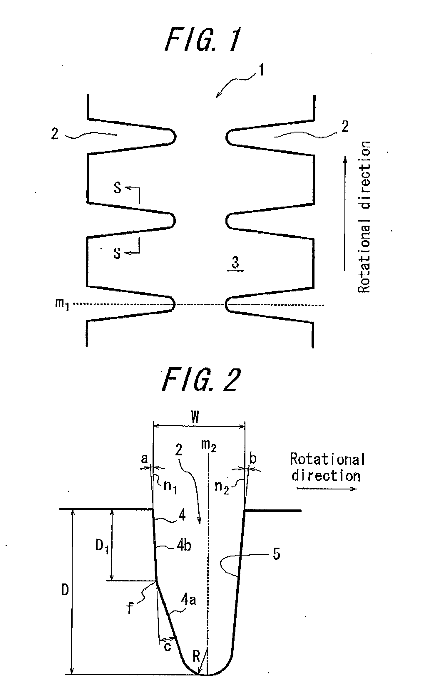
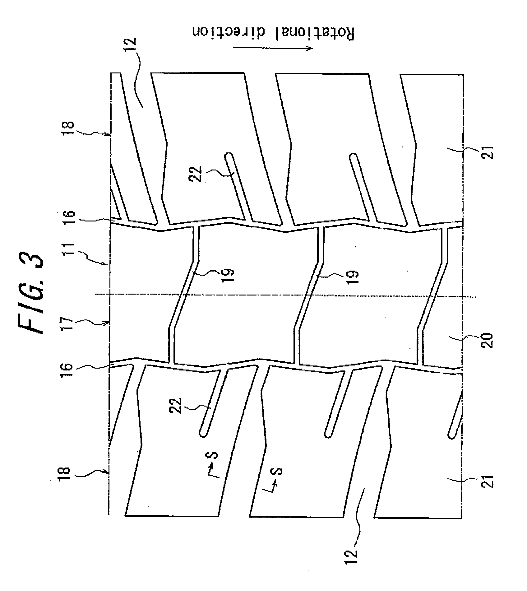
[0053]Radial tires with block patterns and size 46 / 90R57 having the structures as shown in FIG. 2 and FIG. 3, respectively, are prepared. An amount of slip of the trailing edge of the block is measured for each of Example tires 1 and 2 according to the present invention and Comparative Example tire, the characteristics of which tires are changed as shown in Table 1.

Comparative Example tire is prepared basically in the same manner as Examples tires because the former requires no modification from the latter, except that a groove wall of a lug groove of the former should have the conventional structure.

TABLE 1Example Example Comparative tire 1tire 2Example tirea (°)959b (°)959c (°)9150 D (mm)97.197.197.1D1 (mm)5060—

[0054]Each of Example tires 1 and 2 and Comparative Example tire is assembled with a rim of 1.45 (m)×0.74 (m) (57 (inch)×29 (inch)) and inflated at an internal pressure of 700 kPa. Each tire is rotated with load mass of 62000 kg applied thereon, and an amount of slip of the...


PUM


Abstract

The present invention provides a pneumatic radial tire for heavy load, having lug grooves in respective side regions of a tread surface, in which tire an amount of slip of the trailing edge of each of land portions defined by the lug grooves, with respect to a road surface, when the tire is rotated with load applied thereon is advantageously reduced without causing decrease in partial wear resistance of the land portions at a road contact surface thereof and generating cracks at the lug groove bottom. The pneumatic radial tire for heavy load, having a plurality of lug grooves 2 provided in respective side regions of a tread surface 1 to extend in the tread width direction, open at respective side edges of the tread surface 1, and define land portions 3 therebetween, is characterized in that: in a cross section of each lug groove 2 in the width direction thereof, only a groove wall 4 on the step-in side of each land portion 3 is bent at at least one bent point in the depth direction of the corresponding lug groove 2 such that a portion 4a of the groove wall, located on the inner side in the radial direction than the bent point f, is tilted in a direction that narrows a groove width.

Description

TECHNICAL FIELD[0001]The present invention relates to a pneumatic radial tire for heavy load whose rotational direction is specified, and, in particular, to a pneumatic radial tire possessing improved partial wear resistance at land portions defined by lug grooves in respective side regions of a tread surface thereof.BACKGROUND ART[0002]In a pneumatic radial tire for heavy load for use in a vehicle such as a construction vehicle adapted to traveling on unpaved roads, there has been widely used a tread pattern having lug grooves in side regions of a tread surface thereof.[0003]Conventionally, a tire of this type is generally designed such that, in a cross section of a lug groove in the width direction thereof, an angle formed by a groove wall on the step-in side of a land portion, with respect to a line normal to a surface of the land portion, is substantially equal to an angle formed by a groove wall on the kick-out side of the land portion, with respect to a line normal to the surf...

Claims


Application Information

Patent Timeline
Patent Type & Authority Applications(United States)
IPC IPC(8): B60C11/13
CPCB60C11/0316B60C11/1323B60C2011/0383B60C2011/0313
Inventor AOKI, YASUTOSHI
Owner BRIDGESTONE CORP
Why Eureka
Try Eureka