
Pressure measurement module

a technology of pressure measurement module and sensor, which is applied in the direction of fluid pressure measurement, variable capacitor, instruments, etc., can solve the problems of increasing the production cost of the chip, the inability to reduce the distance between the si chip and the capacitor, and the inability to meet the requirements of the integrated emc capacitor

Active Publication Date: 2011-01-27
ROBERT BOSCH GMBH
View PDF6 Cites 28 Cited by
  • Summary
  • Abstract
  • Description
  • Claims
  • Application Information

AI Technical Summary

Benefits of technology

[0005]According to an example embodiment of the present invention, a sensor module, especially a pressure sensor module having integrated capacitors is provided, in which, while using Si chips that are already present, the resistance to electromagnetic interference is increased and, at the same time, the construction of the whole sensor, especially of the pressure sensor, is maintained to be simpler and more flexible. In the construction of the pressure sensor module provided, it is considered important to deviate as little as possible from existing production concepts, that are already used in mass production and have proven themselves.
[0006]The construction provided according to the example embodiment of the present invention, of a pressure sensor module having integrated capacitors, has the advantages over the usually constructed variants that, compared to the variant of integrating the capacitors on the Si chip, a lower chip surface is created, and with that, lower chip costs. Chip-integrated capacitors represent only a compromise, and satisfy the ESD requirements placed on them inadequately or not at all. Lower individual parts costs are created in comparison to the development of a new Si chip.
[0007]The construction provided according to the example embodiment of the present invention has the advantages over the variant, in which the capacitors are adhered to the lead frame in a chamber that does not have pressure applied to it (two-chamber construction), that an improvement in the EMC is achieved by a substantially lesser distance prevails to the Si chip. More flexible construction variants of the sensor are possible, since no external capacitors are used. The process of putting on, adhering and curing is able to be considerably simplified in the production of the pressure sensor module provided according to the present invention, since setting, adhering and curing processes may be omitted. The second chamber present in a two-chamber construction of the pressure sensor module, which was used up to now for accommodating the capacitors, may be used for additional ESD / EMC protective measures. In the second chamber, one may mount, for example, varistors or other electronic components.

Problems solved by technology

This requires, for one thing, a greater expenditure for chip surface, and thereby increases production costs of the chip, and for another thing, the integrated EMC capacitors usually do not fulfill the requirements with respect to the electrostatic discharges (ESD requirements), or do so only inadequately.
The last-named possibility has some disadvantages, such as the construction being less inflexible, since the capacitors cannot be placed at any optional place.
This has the result, in turn, that the distance between the Si chip and the capacitors cannot be decreased at will, which is necessary, however, for optimizing the electromagnetic compatibility.
Chip-integrated capacitors represent only a compromise, and satisfy the ESD requirements placed on them inadequately or not at all.

Method used


Image

  • Pressure measurement module
  • Pressure measurement module
  • Pressure measurement module

Examples


Embodiment Construction

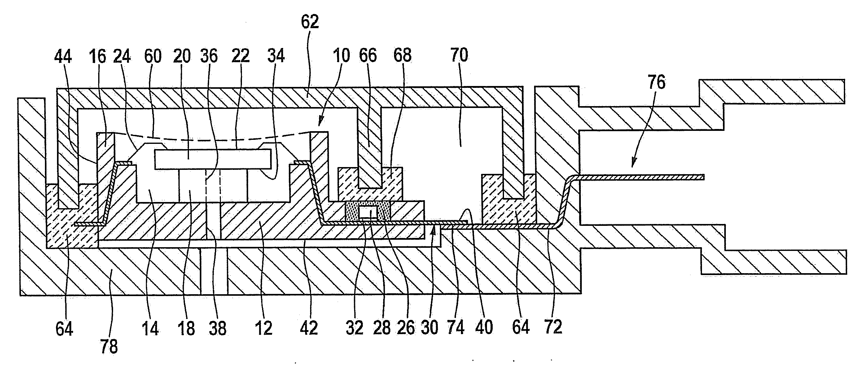
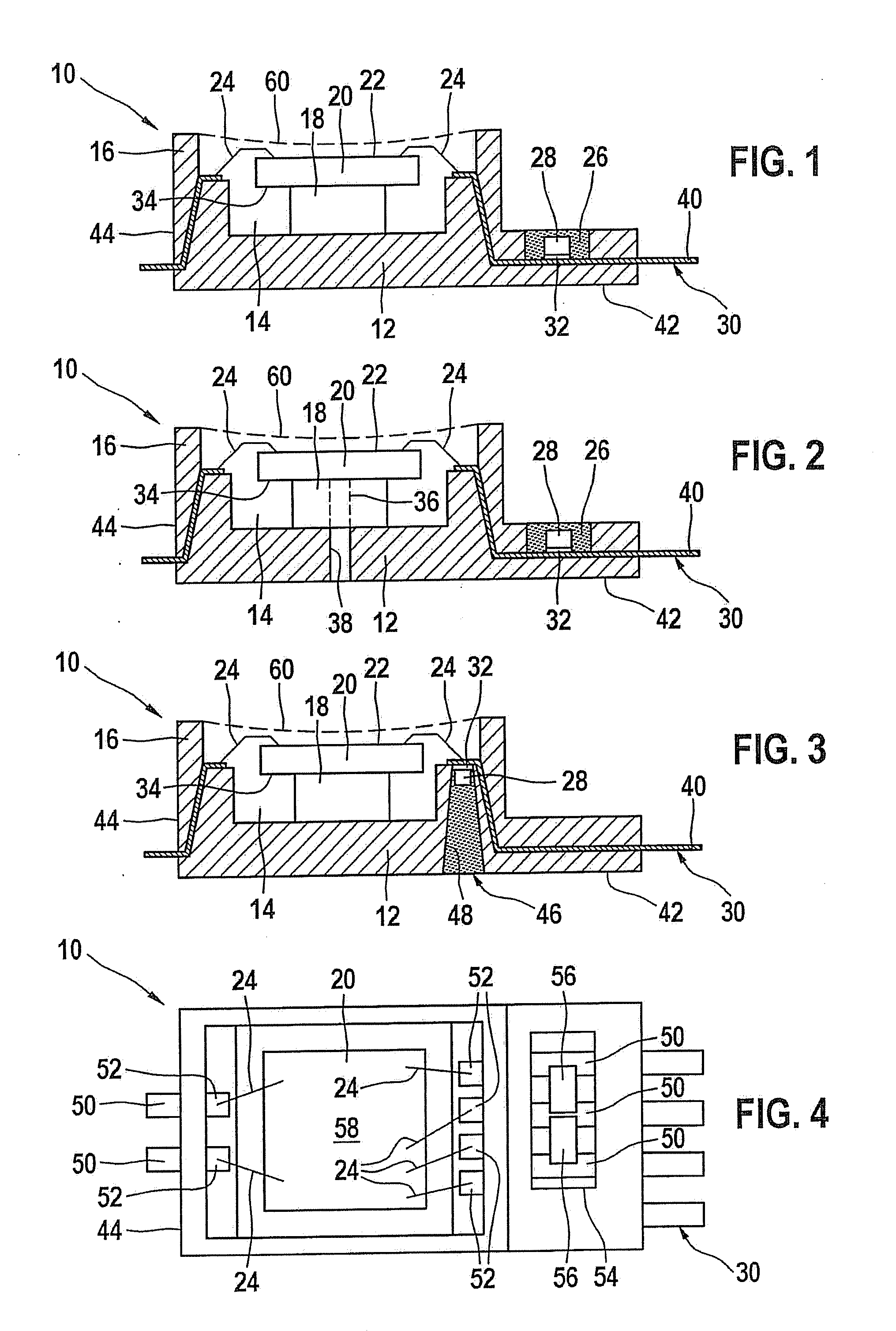
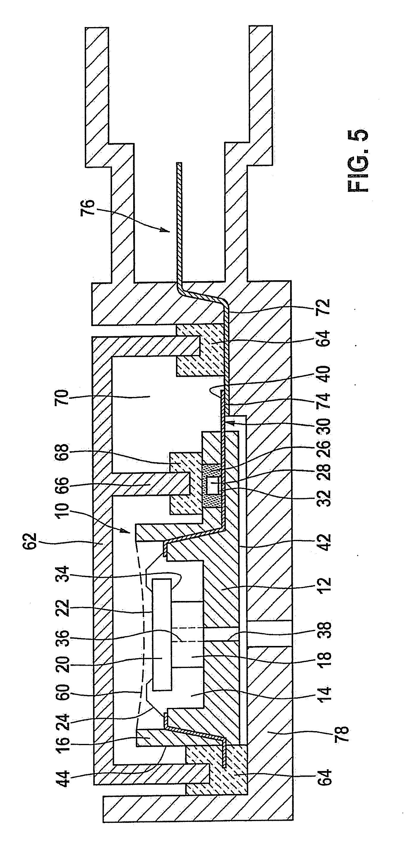
[0019]FIG. 1 shows an example pressure measuring module 10 provided according to the present invention, which is able to be used for recording an absolute pressure.

[0020]FIG. 1 shows that pressure measuring module 10 has a housing 12, whose housing walls 16 border on an inner chamber 14. On the floor of inner chamber 14 there is a pedestal 18, on whose upper side a pressure measuring chip, particularly a silicon pressure measuring chip, is accommodated. Pressure measuring chip 20 has an upper plane surface 22 and a lower side 34. In housing 12 of pressure measuring module 10 there is a lead frame 30, for example, or a number of printed circuit traces 50 (cf. top view according to FIG. 4). Free ends of lead frame 30 or the number of printed circuit traces 50 open out into inner chamber 14 inside housing 12. Plane surface 22 of pressure measuring chip 20 is connected electrically to lead frame 30 or to the number of printed circuit traces 50 via bonding wires 24, depending to the spec...


PUM

PropertyMeasurementUnit
absolute pressureaaaaaaaaaa
relative pressureaaaaaaaaaa
pressureaaaaaaaaaa

Abstract

A pressure measuring module for recording an absolute pressure or a relative pressure. Pressure measuring module includes a housing produced preferably as a premold, in which a pressure measuring chip is accommodated. The latter is contacted electrically either to a lead frame or to at least one printed circuit trace, at least one electronic component being provided, which is connected to a section of the lead frame or of the at least one printed circuit trace, exiting laterally from the housing that is produced as a premold, and is covered by a partition of a cover.

Description

BACKGROUND INFORMATION[0001]German Patent Application No. DE 100 54 013 B4 relates to a pressure sensor module. This includes at least one module housing having a connecting piece in which an opening is situated for a medium that is to be measured. The pressure sensor module furthermore includes a pressure sensor, that is situated in a sensor housing, that is developed to be provided with a sensor housing opening and separately from the module housing, and is protected by a cover mounted on the pressure sensor in the sensor housing. The sensor housing lies in a recess of the module housing, at least partially against the module housing and is held in the recess by a plastic extrusion coating or a sealing compound. A part of the sensor housing surrounding the sensor housing opening lies against the module housing, so that the sensor housing opening completely encloses the opening of the connecting piece. The plastic extrusion coating or the sealing compound completely encloses the se...

Claims


Application Information

Patent Timeline
Patent Type & Authority Applications(United States)
IPC IPC(8): G01L9/00H05K3/00
CPCG01L19/0084Y10T29/49124G01L19/143
Inventor GEBAUER, JANHABIBI, MASOUD
Owner ROBERT BOSCH GMBH
Learn More