
Coated Metallic Sample Peel Test

a technology of coating and peeling, applied in the direction of instruments, measurement devices, scientific instruments, etc., can solve the problems of polymer-metal bond failure in the marine environment, paint blistering and flaking off, exposed underlying metal,

Inactive Publication Date: 2011-01-27
THE UNITED STATES OF AMERICA AS REPRESENTED BY THE SECRETARY OF THE NAVY
View PDF5 Cites 5 Cited by
  • Summary
  • Abstract
  • Description
  • Claims
  • Application Information

AI Technical Summary

Benefits of technology

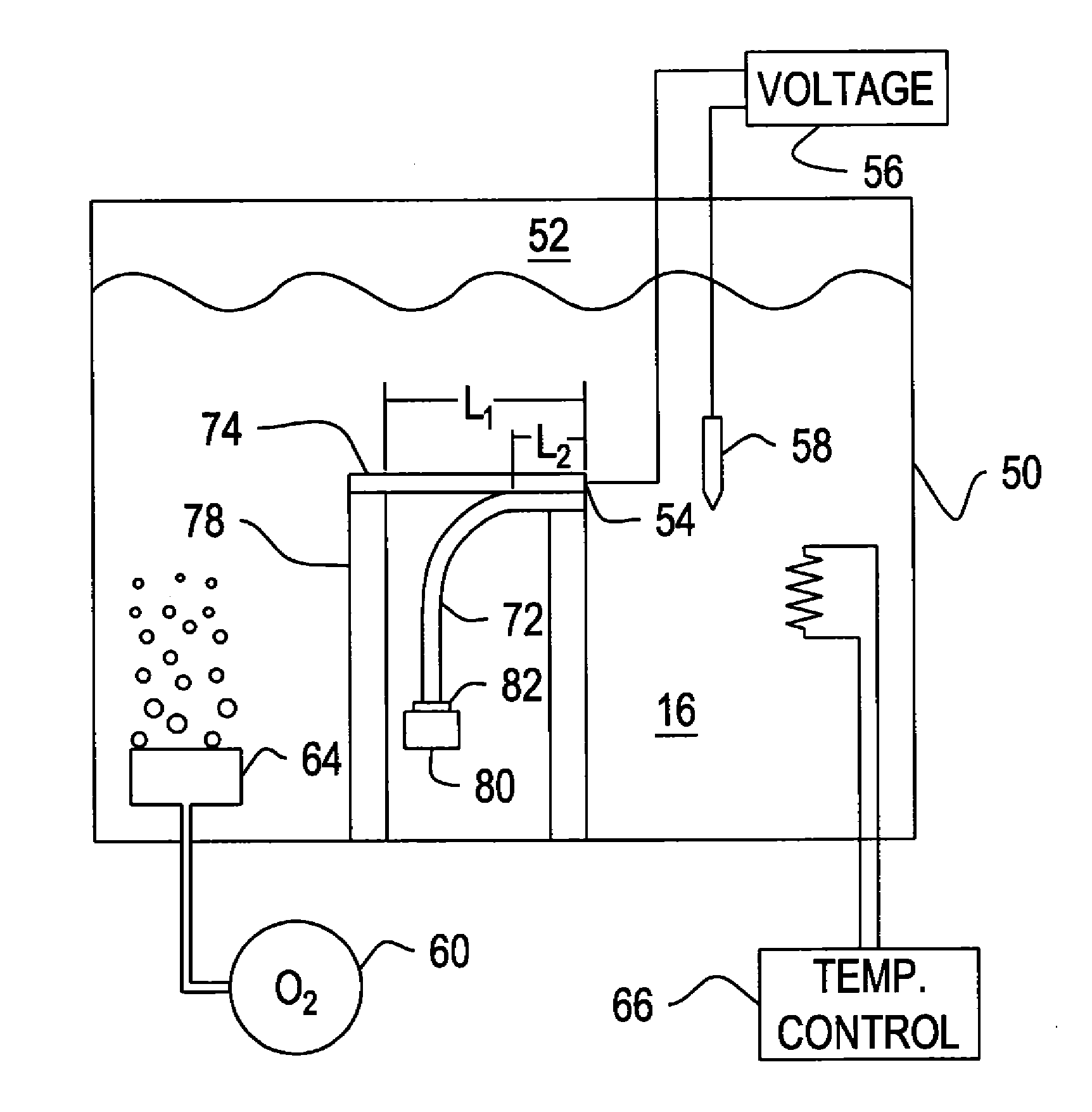
The invention provides a method for testing cathodic delamination of a polymer coated metallic sample. The method involves placing the sample in a tank containing water and an oxygen-containing gas, and increasing the cathodic polarization of the metallic portion of the sample using a voltage source or a sacrificial anode. Dissolved oxygen in the tank can also be increased by adding oxygen under pressure or through an aerator under the water surface. Temperature can also be regulated to accelerate the test speed. The invention also provides a reaction model independent method for calculating activation energy. Overall, the invention allows for faster and more efficient testing of cathodic delamination.

Problems solved by technology

If the polymer in question is paint, then the paint will blister and flake off exposing the underlying metal.
If the polymer is an encapsulant protecting underlying electrical circuitry or devices, then catastrophic failure can result from exposure of vulnerable parts to seawater.
Cathodic delamination is thought to be the major cause of polymer-metal bond failures in the marine environment.
Unfortunately, Ea is often unknown for a given material or set of materials and, therefore it must be determined experimentally.
One problem that develops concerns the numerical value of Ea.
This process can lead to erroneous conclusions from an accelerated life test, because if one is not careful, the observed deterioration may be the result of a process or reaction that occurs only at high temperatures (and thus, would not affect the materials of interest under normal environmental conditions).
The problem is conducting a meaningful accelerated life test on a material with a low Ea for water diffusion and thus, a low reaction acceleration factor.

Method used


Image

  • Coated Metallic Sample Peel Test
  • Coated Metallic Sample Peel Test
  • Coated Metallic Sample Peel Test

Examples


Embodiment Construction

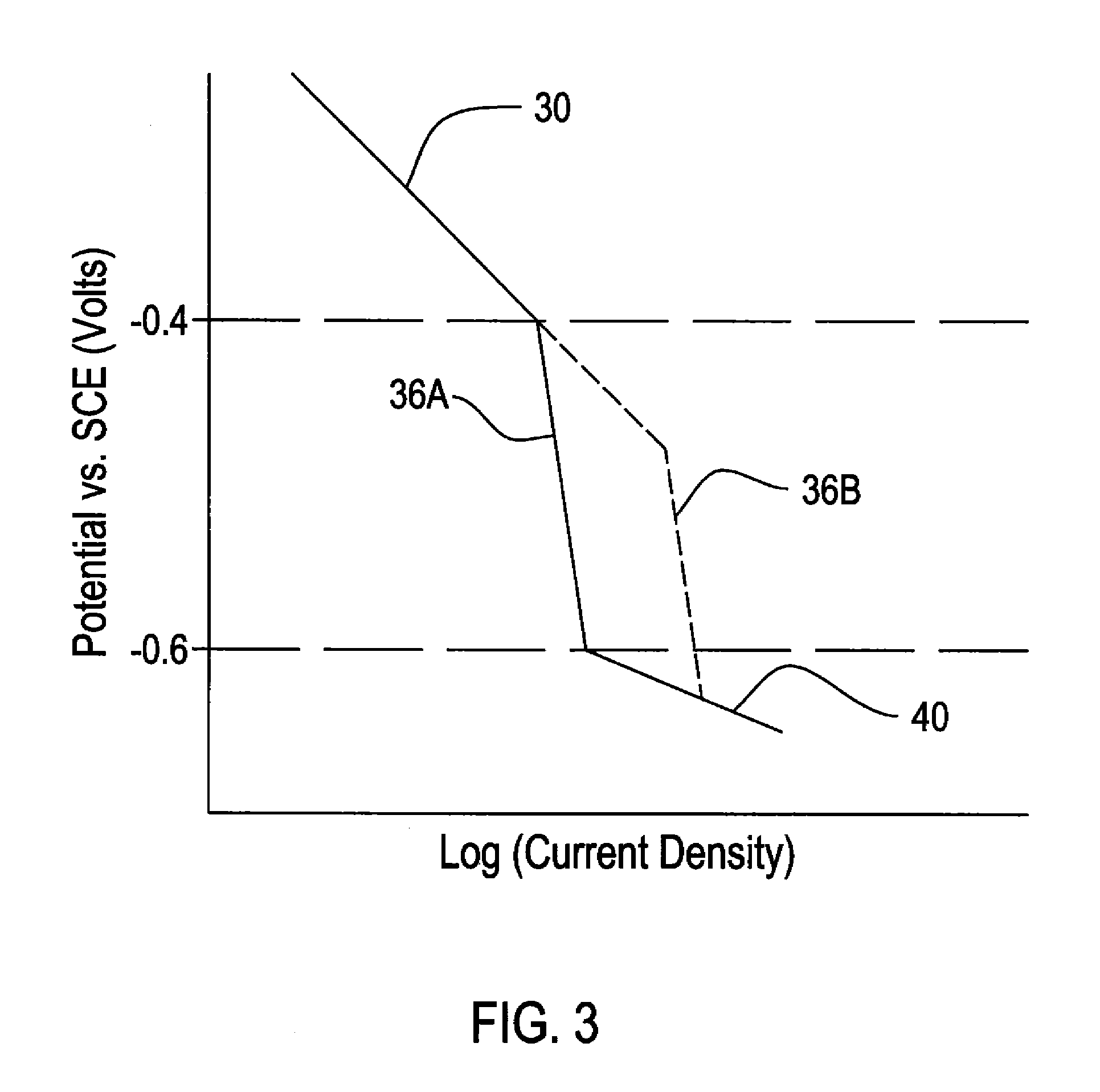
[0024]FIG. 3 shows the general relationship between voltage and current for a corrosion reaction. The cathodic delamination reaction is a corrosion reaction that occurs on a cathodically polarized surface, so it follows this general relationship. As can be seen in FIG. 3 region 30, as polarization (voltage) becomes more cathodic, the current consumed increases. Voltage is measured versus a standard calomel electrode (SCE). Because current consumed is directly proportional to the rate of the corrosion reaction, this means that the reaction rate increases as the polarization becomes more cathodic. However, FIG. 3 also shows that at some potential, region 36A, the current consumed does not change much as the cathodic potential is further increased. In region 36A, the reaction is considered to be “diffusion limited”—i.e., there are insufficient reactants (water and oxygen) on the cathodically polarized surface to support an increase in reaction rate. The available water and oxygen are a...


PUM


Abstract

A method for conducting an accelerated life test of a polymer coated metallic sample includes placing the sample below the water surface in a test tank containing water and an oxygen containing gas. Cathodic polarization of the metallic portion of the sample is increased. This can be by using a voltage source or a sacrificial anode. Dissolved oxygen in the test tank water is also increased. Dissolved oxygen can be increased by providing oxygen under pressure to the tank or through an aerator under the water surface. Temperature can also be regulated to accelerate the test speed. Delamination of the sample is periodically tested through a peel test or by other means. The invention also provides a reaction model independent method for calculating activation energy.

Description

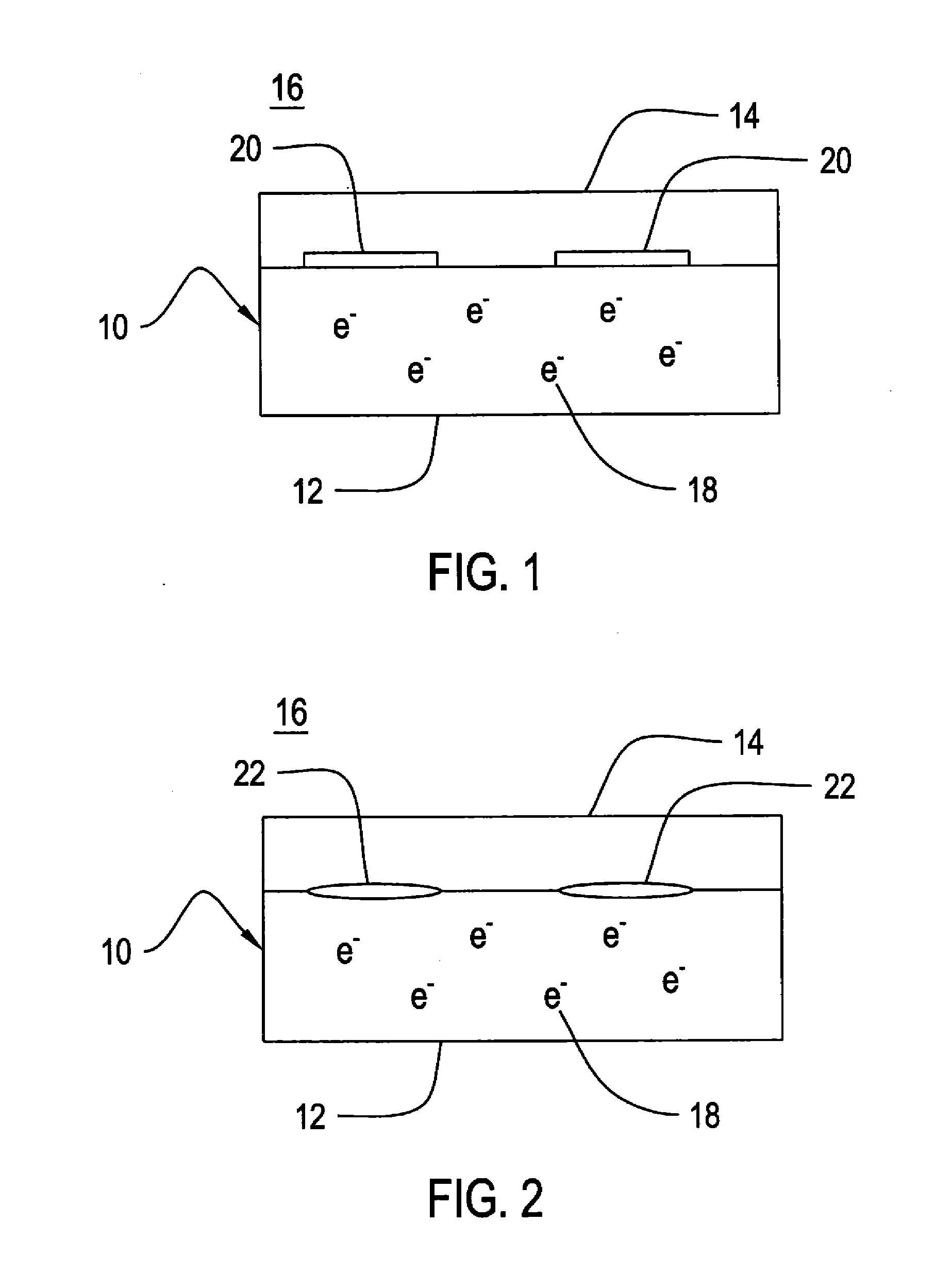
STATEMENT OF GOVERNMENT INTEREST[0001]The invention described herein may be manufactured and used by or for the Government of the United States of America for governmental purposes without the payment of any royalties thereon or therefore.CROSS REFERENCE TO OTHER PATENT APPLICATION[0002]None.BACKGROUND OF THE INVENTION[0003](1) Field of the Invention[0004]The present invention relates to a material testing method for polymers bonded to metals and, more particularly, to a test for cathodic delamination of such materials in water.[0005](2) Description of the Prior Art[0006]Many of the metal-polymer bond failures that occur in the marine environment are caused by a process referred to as “cathodic delamination.” Cathodic delamination is believed to result from the following reaction on a cathodically polarized surface exposed to seawater:2H2O+O2+4e−->4OH−  (1)[0007]FIGS. 1 and 2 show a diagram of cathodic delamination. A material 10 is shown having a cathodically polarized metal sub...

Claims


Application Information

Patent Timeline
Patent Type & Authority Applications(United States)
IPC IPC(8): G01B21/00
CPCG01N17/002
Inventor RAMOTOWSKI, THOMAS S.
Owner THE UNITED STATES OF AMERICA AS REPRESENTED BY THE SECRETARY OF THE NAVY
Learn More