
Control apparatus and control method for robot arm, robot, control program for robot arm, and integrated electronic circuit

a technology of electronic circuit and control apparatus, applied in the direction of electric programme control, program control, instruments, etc., can solve the problems of long time, time-consuming troublesome tasks, and inability to provide an efficient process, and achieve the effect of easy correction

Active Publication Date: 2011-01-20
PANASONIC CORP
View PDF6 Cites 57 Cited by
  • Summary
  • Abstract
  • Description
  • Claims
  • Application Information

AI Technical Summary

Benefits of technology

"The present invention provides a control apparatus and method for a robot arm that allows for easy and efficient training of the robot by the operator. The control apparatus includes an operation information acquiring unit, a grabbed position detection unit, a characteristic information acquiring unit, and an operation correcting unit. The control method switching unit switches control methods of the robot arm based on the grabbed position and the characteristic information. The operation correcting unit corrects information relating to the force of the operation based on the manipulation of the person. This invention allows for quicker training of the robot arm and reduces the time and effort required for training."

Problems solved by technology

In Patent Document 1, however, since all the teaching points need to be taught by the teaching person, the teaching process takes long time, resulting in time-consuming troublesome tasks.
Moreover, in the industrial field, upon revising one portion of taught movements, the revision needs to be made through a programming process by using a remote control apparatus referred to as a teaching pendant, or all the operations need to be, taught all over again from the beginning, failing to provide an efficient process.
Moreover, a combined use of the programming process by the remote control apparatus such as the teaching pendant causes an increase in manipulation steps, and learning of programming languages is required, with the result that this method becomes very difficult for amateurs at home.
Moreover, the home environment varies from moment to moment, and it is difficult to predict all the environmental variations at the time of teaching, and even if the detections can be made by providing many censors, there is a possibility of erroneous operations when the detection precision is not 100%.

Method used


Image

  • Control apparatus and control method for robot arm, robot, control program for robot arm, and integrated electronic circuit
  • Control apparatus and control method for robot arm, robot, control program for robot arm, and integrated electronic circuit
  • Control apparatus and control method for robot arm, robot, control program for robot arm, and integrated electronic circuit

Examples


first embodiment

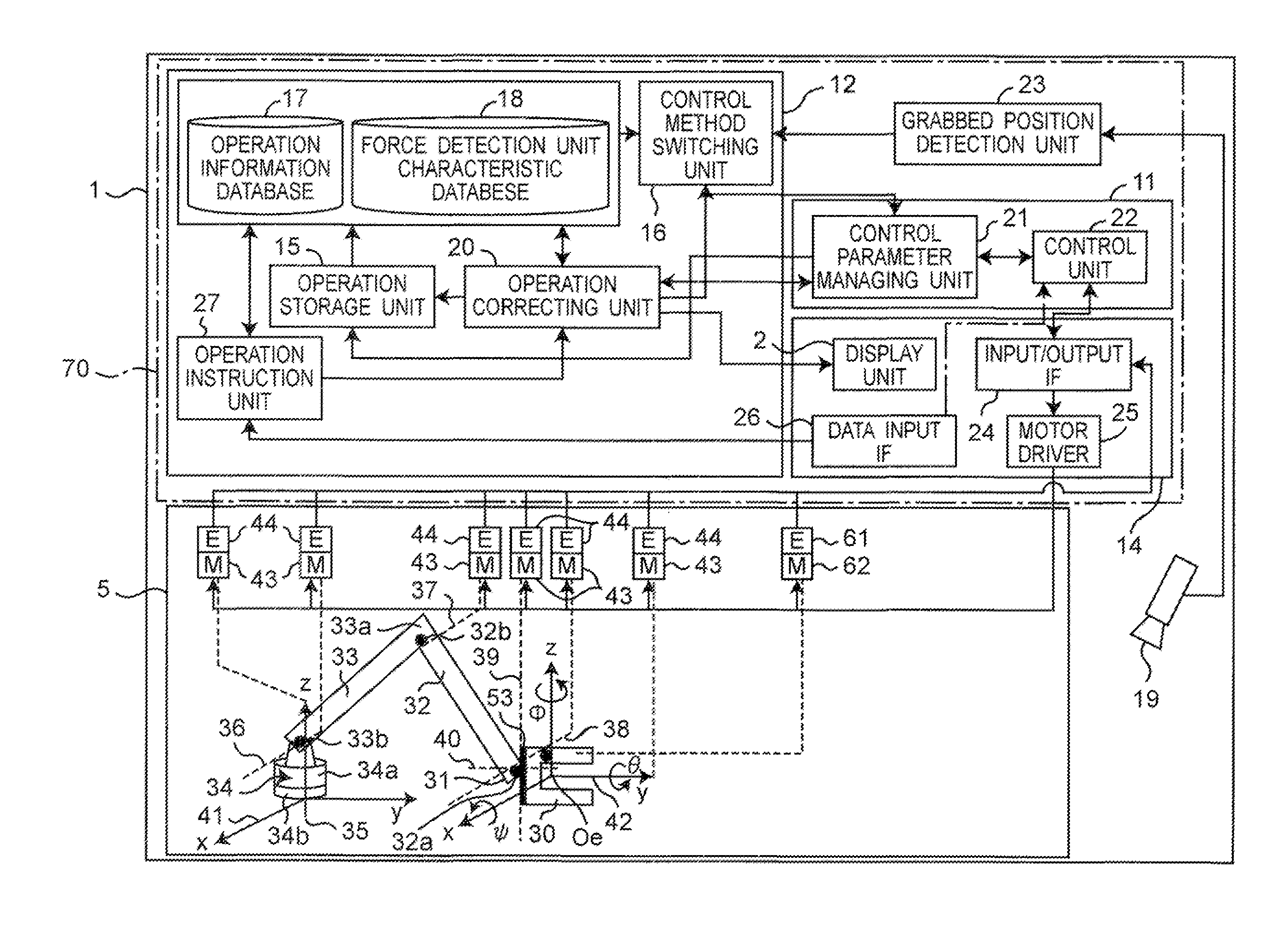
[0167]First, the following description will discuss a structure of a robot system 1 provided with a robot arm control apparatus in a first embodiment of the present invention. FIGS. 1 and 2 are views that schematically show the robot system 1 provided with a robot arm 5 and its control apparatus 70 of the first embodiment of the present invention.

[0168]As shown in FIG. 1, the robot arm 5 of the robot system 1 is attached to a wall surface 7a of, for example, a kitchen in a home or a work bench 7 such as a table. The base end 5a of the robot arm 5 is shiftably supported on a rail 8 secured onto the wall surface 7a so that the robot arm 5 is allowed to move on the rail 8 in lateral directions (for example, in horizontal directions) along the rail 8, by a force of a person 4.

[0169]The robot system 1 is a system for carrying out a job in a home that is executed by the robot arm 5 and the person 4 in cooperation with each other, for example, a job for wiping off stains 91 in the kitchen ...

second embodiment

[0312]Since the basic structure of a control apparatus of the robot arm in a second embodiment of the present invention is the same as that of the first embodiment, explanations for the common portions will be omitted, and the following description will discuss only different portions in detail.

[0313]In the same manner as in the first embodiment, as shown in FIGS. 16A and 16B, the following explanation will be given by exemplifying a state in which, when a wiping job is carried out by using a robot system 1, the manipulation is carried out with one robot arm 5 being grabbed by a plurality of persons 4A, 4B, as shown in FIG. 18, or the manipulation is carried out with a plurality of portions of one robot arm 5 being grabbed by one person 4. FIG. 19 is a view showing specific structures of a robot arm 5 that is a target to be controlled and a control apparatus 70 for the robot arm 5, which form the robot system 1 in the second embodiment. Since the robot arm 5, the peripheral apparatu...

third embodiment

[0328]Since the basic structure of a control apparatus of the robot arm in a third embodiment of the present invention is the same as that of the first embodiment, explanations for the common portions will be omitted, and the following description will discuss only different portions in detail.

[0329]As shown in FIGS. 22A to 22D, the following description will exemplify a state in which a plurality of robot arms 5A and 5B are operated. FIG. 22A shows a job in which, for example, upon cooking, dough is rounded into balls or dough is extended, that a job in which a plurality of robot arms 5A and 5B are applying forces to an object 47 in cooperation with each other. Moreover, FIG. 22B shows a job in which, upon cooking, dough is kneaded, or, for example, upon carrying out a wiping job, forces are simultaneously applied onto a contact surface by a plurality of robot arms 5A and 5B. The following description will exemplify an arrangement in which, during such a job, as shown in FIGS. 22C ...


PUM


Abstract

After switching a control method for a robot arm based upon characteristic information containing pieces of information relating to a grabbed position of the robot arm by a person and a presence / absence of detection of a force as well as to presence / absence of influences from a drag, during an operation of the robot arm, by a control method switching unit, information relating to the force of operation information is corrected by an operation correcting unit in response to a manipulation of the person.

Description

TECHNICAL FIELD[0001]The present invention relates to a control apparatus and a control method for a robot arm, used for generating operations of a robot as well as for teaching the operations to the robot, a robot provided with such a control apparatus for a robot arm, a control program for a robot arm, and an integrated electronic circuit.BACKGROUND ART[0002]In recent years, house-service robots, such as nursing robots or housekeeping support robots, have been vigorously developed. Different from the industrial robot, the house-service robot is manipulated by amateurs in home; therefore, it is necessary to easily teach operations to the robot. Moreover, since there are various operation environments in which the robot carries out a job depending on homes, it is necessary for the robot to flexibly adjust to the corresponding home environment.[0003]For example, a teaching method for the robot device has been proposed in which a force sensor is attached to the wrist or the like of a ...

Claims


Application Information

Patent Timeline
Patent Type & Authority Applications(United States)
IPC IPC(8): B25J9/02
CPCB25J9/0003G05B19/42B25J13/085
Inventor TSUSAKA, YUKOOKAZAKI, YASUNAO
Owner PANASONIC CORP
Learn More