Position adjusting means for hot runner nozzles, adjusting method and use thereof
a technology of adjusting means and hot runner nozzles, which is applied in the field of runner systems, can solve the problems of not being able to adjust, the mold design is optimized, and the hot runner system with fixed configuration cannot be applied to other molds with different nozzle arrangements, etc., and achieves reasonable configuration, improved runner configuration, and better fulfill manufacturing
- Summary
- Abstract
- Description
- Claims
- Application Information
AI Technical Summary
Benefits of technology
Problems solved by technology
Method used
Image
Examples
embodiment 1
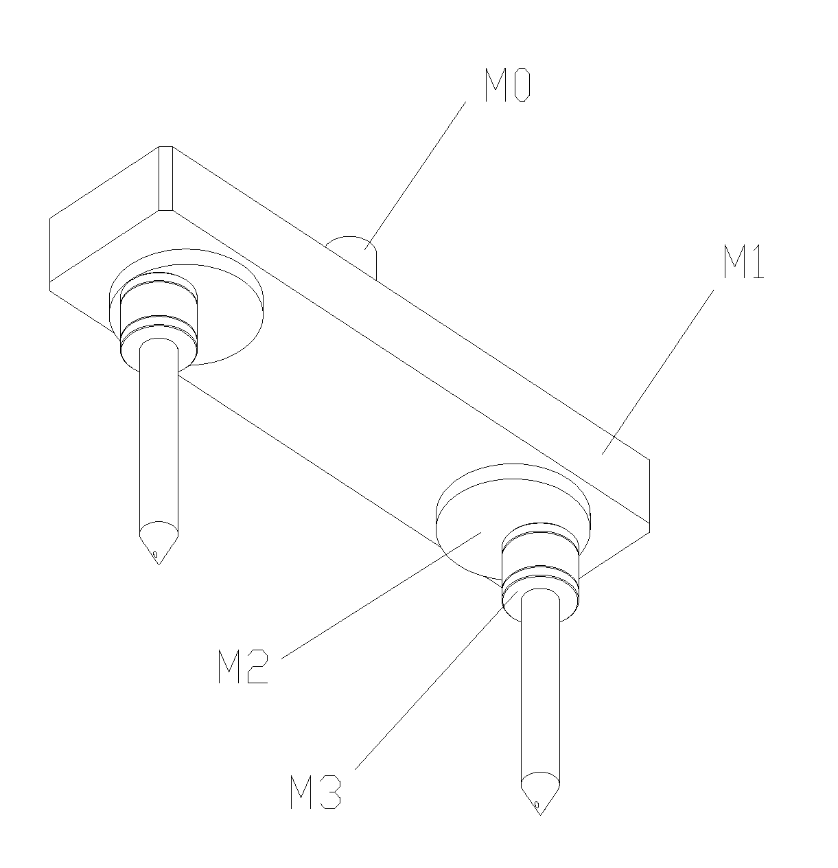
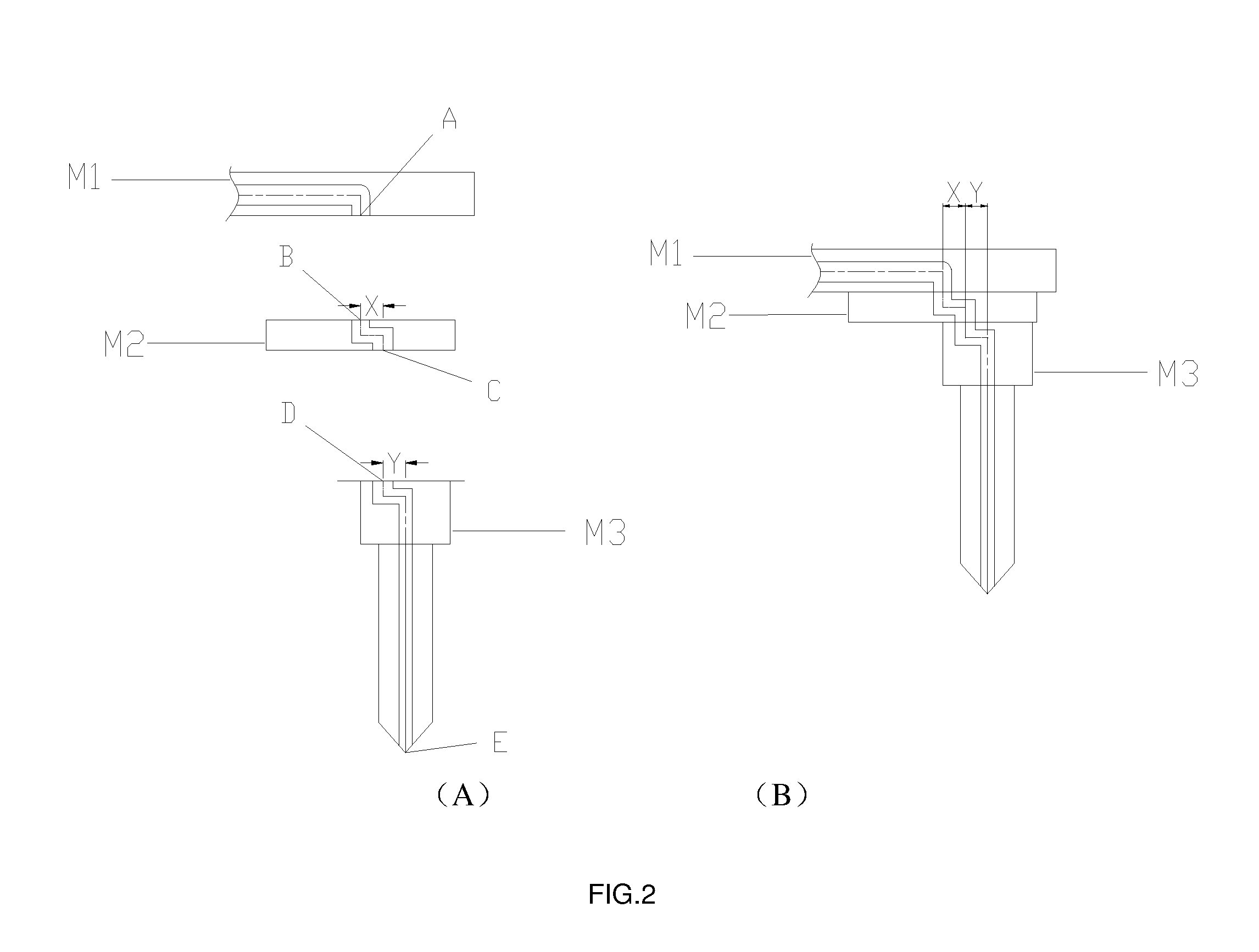
[0046]FIGS. 4-6 illustrate the structure of the present invention. As illustrated in FIG. 4, the present position adjusting means for hot runner nozzles comprises a main inlet M0, a manifold M1, a rotating transitional member M2 and a nozzle M3. The manifold M1, the rotating transitional member M2 and the nozzle M3 are each disposed with an inlet and an outlet. The main inlet M0 is connected with an injection outlet of an injection molding machine. The main inlet M0 is also connected with the inlet of the manifold M1. The manifold M1 is disposed with runners therein. As illustrated in FIGS. 5 and 6, the rotating transitional member M2 is disposed with an inlet B and an outlet C. The inlet B and the outlet C each has a symmetry axis and the two symmetry axes are disposed in parallel with and spaced apart from each other for a particular distance (X), as illustrated in FIG. 5. The inlet B of the rotating transitional member M2 and the outlet A of the manifold M1 are connected to each ...
embodiment 2
[0052]FIGS. 7-8 illustrate another structure of the present invention. As illustrated in FIG. 7, the present position adjusting means for hot runner nozzles comprises a manifold 701, a first rotating transitional member 702, a second rotating transitional member 703 and a nozzle 704. Each of the manifold 701, the first rotating transitional member 702, the second rotating transitional member 703 and the nozzle 704 is disposed with runners, an inlet and an outlet. The manifold 701 has a lower side which is disposed with an outlet with a center F. The outlet is disposed with a circular recess for receiving a circular positioning ring 705. The first rotating transitional member 702 has an upper side with two ends which is disposed with an inlet G and an outlet H respectively. The inlet G and the outlet H are disposed with a circular recess for receiving the circular positioning ring 705. As illustrated in FIG. 8, the distance between the inlet G and the outlet H is X1. The second rotat...
embodiment 3
[0054]The present embodiment has similar structure as Embodiment 2 with the following exceptions (as illustrated in FIGS. 9-10):
[0055]As illustrated in FIG. 9, the first rotating transitional member 902 has an upper side which is disposed with an inlet G at an end and a lower side which is disposed with an outlet H at another end. The inlet G and the outlet H are each disposed with a circular recess for receiving a circular positioning ring 905. The distance between the inlet G and the outlet H is X1 (as shown in FIG. 10).
[0056]The second rotating transitional member 903 has an upper side which is disposed with an inlet I at an end and a lower side which is disposed with an outlet J at another end. The inlet I is disposed with a circular recess for receiving a circular positioning ring 905. The distance between the inlet I and the outlet J is Y1.
[0057]The manifold 901 and the first rotating transitional member 902 are connected to each other in a rotatable and sealed manner via the ...
PUM
| Property | Measurement | Unit |
|---|---|---|
| distance | aaaaa | aaaaa |
| degree of rotation | aaaaa | aaaaa |
| circumference | aaaaa | aaaaa |
Abstract
Description
Claims
Application Information
 - R&D
- Intellectual Property
- Life Sciences
- Materials
- Tech Scout
- Unparalleled Data Quality
- Higher Quality Content
- 60% Fewer Hallucinations
Browse by: Latest US Patents, China's latest patents, Technical Efficacy Thesaurus, Application Domain, Technology Topic, Popular Technical Reports.
© 2025 PatSnap. All rights reserved.Legal|Privacy policy|Modern Slavery Act Transparency Statement|Sitemap|About US| Contact US: help@patsnap.com


