Eureka AIR delivers breakthrough ideas for toughest innovation challenges, trusted by R&D personnel around the world.

Hybrid vehicle system with indirect drive

a hybrid vehicle and indirect drive technology, applied in the direction of battery/fuel cell control arrangement, electric devices, gearing, etc., can solve the problems of not being able to adapt to use on the existing wheel, reducing the space available for and reducing the space provided for the vehicle's brakes and suspension components

Inactive Publication Date: 2011-01-20
POULSEN PEDER ULRIK
View PDF42 Cites 31 Cited by
  • Summary
  • Abstract
  • Description
  • Claims
  • Application Information

AI Technical Summary

Benefits of technology

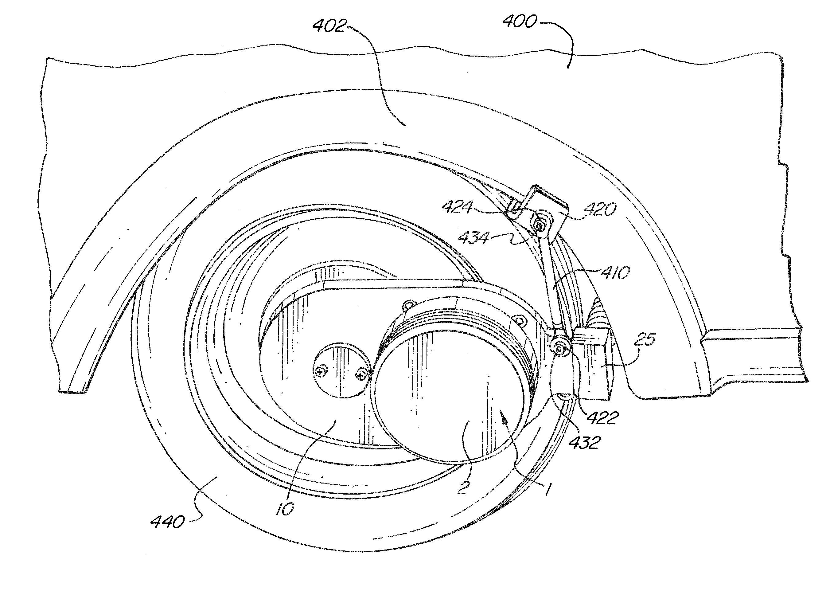
[0011]Accordingly, it is a principal objective of the invention to provide a geared electric drive-assist system to be added to conventional vehicles. For example, a system according to the invention may comprise electric motors each coupled to a speed reduction mechanism such as a gearbox, belt drive or roller chain in a step down configuration. The electric motor(s) is / are designed to bolt onto the vehicle, and the speed reduction mechanism connects the electric motor to the wheel so that the electric motor can impart a rotational force on the wheel. The electric motor can mount off center of the wheel. In one example, the speed reduction mechanism allows the use of a motor that rotates 3 to 4 times faster than the wheel. An indirect drive system provides several advantages over a direct drive system. The motor used can be considerably smaller for a given output power. A smaller motor brings along cost savings as well as weight savings. The weight savings coupled with an off center mounting location of the motor adds considerably less to the un-sprung mass in relation to a direct drive system dependent on the mounting location relative to the wheel center and the system attachment point. For example, if the motor is centered between the system attachment point and the wheel center, only 50% of the weight can be considered un-sprung mass. This advantage allows the indirect drive system to be installed with less impact on the vehicle handling characteristics.
[0013]It is a further objective of the invention to provide an indirect electric drive system, which is sufficiently simple to be retrofitted to an existing vehicle by an auto repair shop or by a moderately mechanically proficient owner. A further objective of the invention is to propose inexpensive factory modifications to vehicles originally designed with only a combustion engine (e.g., gasoline or diesel), in order to facilitate addition of a drive system according to the invention. The indirect electric drive-assist system may be added by the factory during production, at purchase as a dealer option or at a later date whenever the owner may decide to do so.
[0023]Also provided is a hybrid vehicle indirect drive system including at least one electrically powered motor, a speed reduction mechanism coupled to the electrically powered motor and a wheel of a vehicle, the speed reduction mechanism including a housing, and a battery connected to the at least one electrically powered motor for supplying power to the electrically powered motor. A connection rod attaches the housing of the speed reduction mechanism to the vehicle via an attachment point on the vehicle, the connection rod providing sufficient degrees of freedom to absorb relative movement between the wheel and the vehicle.

Problems solved by technology

However, prior art systems such as the one disclosed in the Kubo patent require substantial modification and / or remanufacture of the vehicle power train to be implemented.
However, the process requires the machining of components to fit the particular vehicle and requires modifications to the primary drive system of the vehicle including its drive shaft and transmission.
This design is disadvantageous because it substantially reduces the space available for brakes and suspension components, and requires an entirely new custom wheel.
Each of these prior art in-wheel motors reduce the space provided for the vehicle's brakes and suspension components, and are not also adaptable for use on a vehicle's existing wheel.
This system does not disclose or contemplate a motor coupled to a speed reduction mechanism.
The drawbacks to a direct drive motor include, considerable addition to the unsprung mass of the vehicle wheel, which can cause un-desired changes in vehicle handling characteristics.
Although simple in nature, a direct drive system becomes bulky and heavy in relation to their rated power and torque, because the rotational speed of the motor is limited by the rotational speed of the wheel.

Method used


Image

  • Hybrid vehicle system with indirect drive
  • Hybrid vehicle system with indirect drive
  • Hybrid vehicle system with indirect drive

Examples


Embodiment Construction

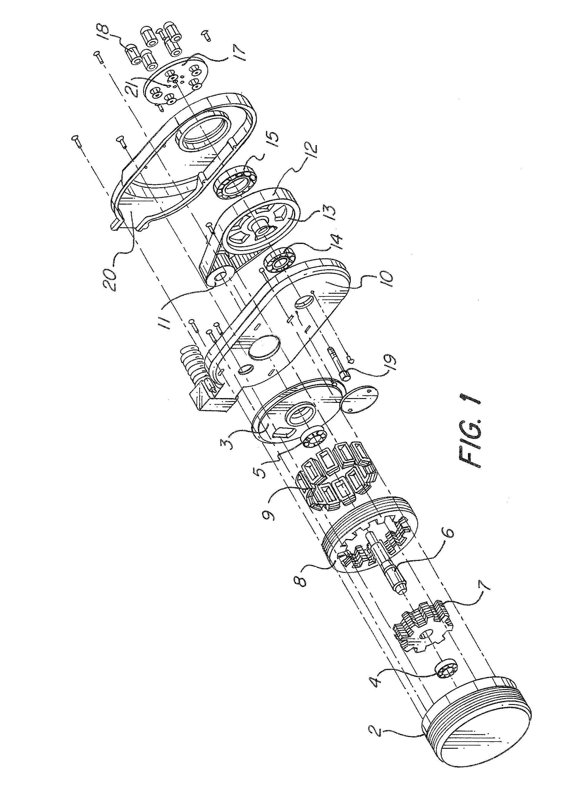
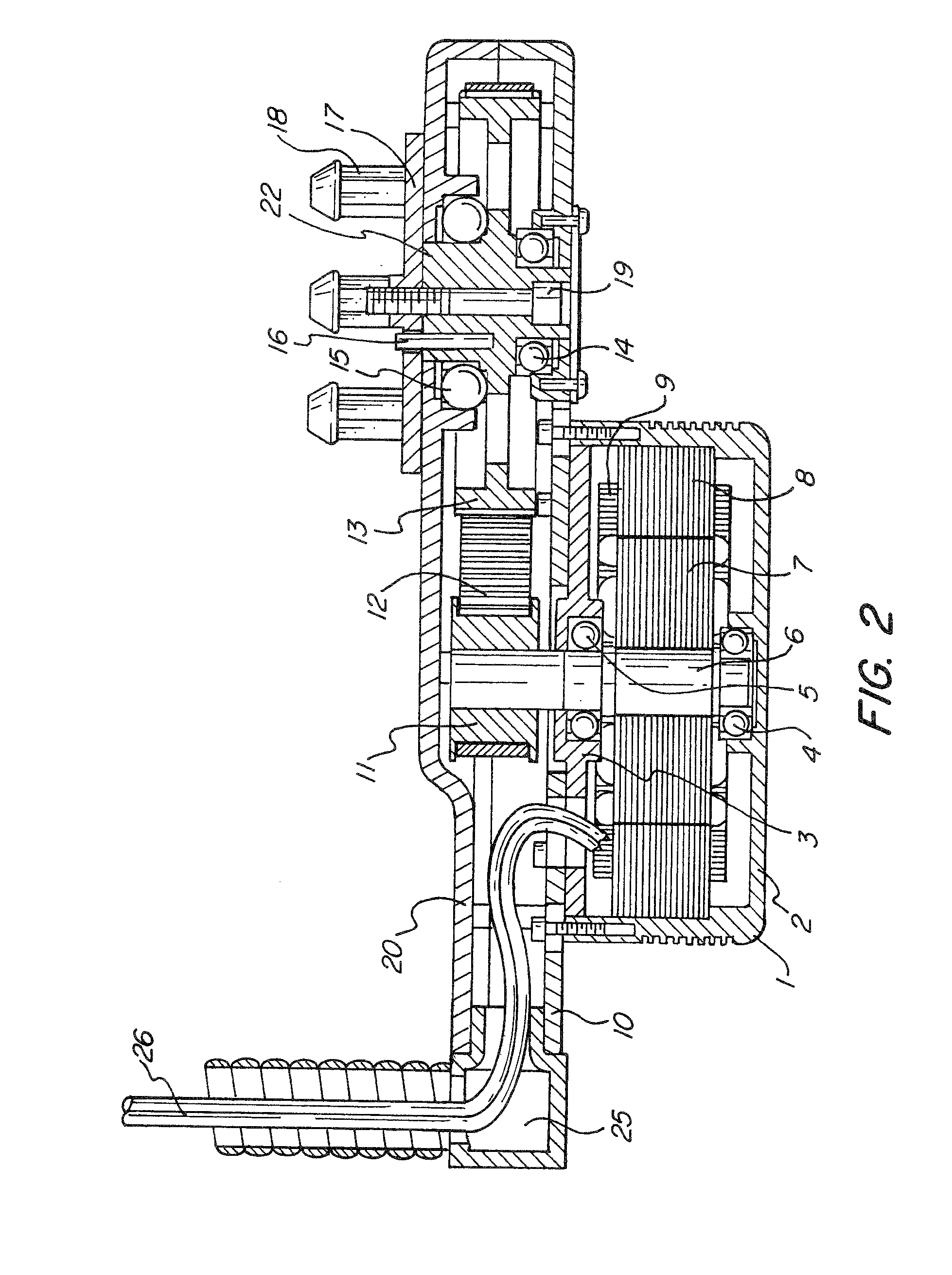
[0036]FIG. 1 is an exploded view of one embodiment of an indirect electric drive system according to one exemplary embodiment of the present invention. The exemplary embodiment is a belt driven design, however, as discussed in more detail below, the system may employ a number of other types of speed reduction mechanisms such as a V belt, roller chain, and sprockets or gears as well as other transmission elements all within the scope of the invention.

[0037]The system shown in FIG. 1 includes a motor 1, such as a Switched Reluctance DC motor, comprising a housing 2 and a cover 3. Other types of motors, such as an AC induction motor, a DC shunt motor, and a permanent magnet brushless DC motor may also be used. The housing 2 and cover 3 hold ball bearings 4 and 5, respectively. A motor shaft 6 is supported by the bearings 4 and 5.

[0038]A laminated rotor 7 is mounted to shaft 6. The motor 1 includes a stator 8 composed of stacked laminations with inwardly protruding poles, each pole bein...


PUM


Abstract

A plug-in hybrid vehicle drive system, including an internal combustion engine for driving one or more wheels of a vehicle, at least one on-wheel electrically powered motor, the motor coupled to a speed reduction mechanism, the speed reduction mechanism coupled to a vehicle wheel for driving at least one wheel of the vehicle, a battery located in the vehicle and connected to the at least one on-wheel motor for supplying power to the on-wheel motor, a battery charger including an AC / DC power converter, and an AC outlet connector in communication with the battery charger for receiving power from an external source.

Description

CROSS-REFERENCE TO RELATED APPLICATIONS[0001]This application is a continuation-in-part of co-pending U.S. patent application Ser. No. 11 / 875,557, filed Oct. 19, 2007, which claims the benefit of, under 35 U.S.C. 119(e), U.S. Provisional Patent Application No. 60 / 919,038, filed Mar. 20, 2007, each of which are hereby incorporated herein by reference in their entirety.FIELD OF THE INVENTION[0002]The present invention relates to hybrid drive vehicles generally and more particularly to plug-in hybrid vehicles.BACKGROUND OF THE INVENTION[0003]Some hybrid drive vehicles, known as hybrid electric vehicles (“HEV”), incorporate an internal combustion engine as well as at least one electric motor and a bank of batteries. Contrary to all-electric vehicles, in these first generation hybrids the batteries are not charged from the utility grid but from a generator driven by the engine. The addition of the electric motor improves fuel economy by enabling the engine to run at its most economical s...

Claims


Application Information

Patent Timeline
IPC IPC(8): B60K6/48F16H35/00F16H7/00
CPCB60K6/26B60K7/0007B60K17/043B60K2007/0038B60K2007/0061B60L2220/46Y10T74/19H02K7/006H02K7/14H02K21/24Y02T10/641Y02T90/16H02K5/1735B60L7/14B60L15/2009B60L15/2045B60L2210/30B60L2210/40B60L2220/14B60L2240/421B60L2240/423B60L2240/441B60L50/16B60L53/14B60L58/21Y02T10/64Y02T10/70Y02T10/7072Y02T10/72Y02T90/14Y02T90/12
Inventor POULSEN, PEDER ULRIK
Owner POULSEN PEDER ULRIK
Why Eureka
Eureka Blog
Learn More