Coater and method of manufacturing plastic lens
a coating device and plastic lens technology, applied in the field of coating devices, can solve the problems of decreasing the the inability to obtain the coating film having sufficient thickness, and the inability to prevent dust, so as to reduce the uneven thickness of the coating film
- Summary
- Abstract
- Description
- Claims
- Application Information
AI Technical Summary
Benefits of technology
Problems solved by technology
Method used
Image


Examples
first embodiment
(1) First Embodiment
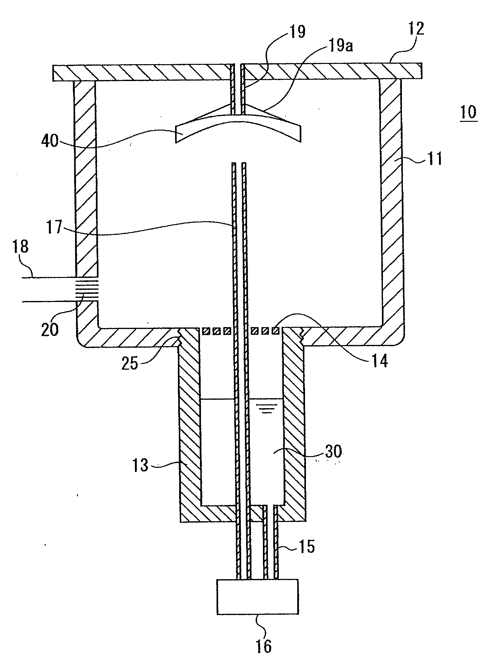
[0032]FIG. 1 is a cross section schematically showing the configuration of a coating device according to a first embodiment of the present invention. A treatment device 10 includes, for example, a substantially cylindrical treatment tank 11, a lid 12 covering an upper portion of the treatment tank 11 so that the treatment tank 11 is hermetically sealed, and a containing tank 13 connected to a lower portion of the treatment tank 11 to contain coating material. The containing tank 13 is substantially cylindrical having a radius smaller than that of the treatment tank 11, for example. Further, an upper opening of the containing tank 13 is connected to the bottom of the treatment tank 11, and it is preferred, but not required, that a net 14 is arranged in an opening provided between the treatment tank 11 and the containing tank 13 so that foreign matter, for example, does not enter the containing tank 13.
[0033]A substrate holder 19 for holding a substrate 40 such as ...
second embodiment
(2) Second Embodiment
[0043]Next, a coating device according to a second embodiment of the present invention will be described below. FIG. 2 is a cross section schematically showing the configuration of a coating device according to the present embodiment. Note that, like components shown in FIG. 2 are denoted by like numerals as of FIG. 1 and the explanation thereof will not be repeated. In the present embodiment, in addition to an exhaust pipe 21, as the partial pressure reducer, provided in the lower portion of the treatment tank 11 similar to the first embodiment, an introducing pipe 22 is provided in an upper portion of the treatment tank 11. The introducing pipe 22 serves as a gas introducing section for introduced a gas (such as an inert gas, the air or the like) into the coating device 10 so that total pressure inside the coating device 10 is maintained constant. Since not only the partial pressure reducer, which discharges the gas inside the treatment tank 11, but also the g...
third embodiment
(3) Third Embodiment
[0046]Next, a coating device according to a third embodiment of the present invention will be described below. The present embodiment is configured by replacing the net 14 arranged between the treatment tank 11 and the containing tank 13 of the coating device according to the first and second embodiments with a partition 23. FIG. 3 shows an example in which the present embodiment is applied to the coating device described in the first embodiment, and FIG. 4 shows an example in which the present embodiment is applied to the coating device described in the second embodiment. Note that, like components shown in FIGS. 3 and 4 are denoted by like numerals as of FIGS. 1 and 2, and the explanation thereof will not be repeated.
[0047]In the present embodiment, the partition 23 of the bottom of the treatment tank 11 for partitioning the treatment tank from the containing tank 13 has a funnel shape which is gradually recessed downward from the peripheral portion toward the ...
PUM
| Property | Measurement | Unit |
|---|---|---|
| partial pressure | aaaaa | aaaaa |
| vapor pressure | aaaaa | aaaaa |
| partial pressure | aaaaa | aaaaa |
Abstract
Description
Claims
Application Information
 - R&D
- Intellectual Property
- Life Sciences
- Materials
- Tech Scout
- Unparalleled Data Quality
- Higher Quality Content
- 60% Fewer Hallucinations
Browse by: Latest US Patents, China's latest patents, Technical Efficacy Thesaurus, Application Domain, Technology Topic, Popular Technical Reports.
© 2025 PatSnap. All rights reserved.Legal|Privacy policy|Modern Slavery Act Transparency Statement|Sitemap|About US| Contact US: help@patsnap.com