
Electrostatic loudspeaker

a loudspeaker and electrostatic technology, applied in the direction of electrical transducers, transducer details, microphone structure associations, etc., can solve the problems of heavy vibration system, limited application of moving coil loudspeakers in portable products, and low frequency respons

Active Publication Date: 2011-01-13
MEMSENSING MICROSYST SUZHOU CHINA
View PDF7 Cites 7 Cited by
  • Summary
  • Abstract
  • Description
  • Claims
  • Application Information

AI Technical Summary

Benefits of technology

The present invention relates to an electrostatic loudspeaker with improved sound quality. The technical effects of the invention include the use of a backplate with a metal film acting as one electrode of a capacitor, a diaphragm with a metal film acting as the other electrode of the capacitor, a back chamber with a substrate and an insulative spacer for joining edge portions of the diaphragm and the substrate, a driving circuit element mounted on the substrate for converting electrical signals into driving signals to drive the diaphragm to vibrate and sound, and a plurality of connection paths for electrically connecting the driving circuit element with the metal films of the backplate, the diaphragm, and the exterior input pads. Additionally, the invention includes a shielding case enclosing the connection paths. These technical features enhance the sound quality and stability of the electrostatic loudspeaker.

Problems solved by technology

However, the vibration system has a heavy quality which limits the application of the moving-coil loudspeaker in the portable products.
In addition, the frequency response is not flat and has worse performance in high-range frequency.

Method used


Image

  • Electrostatic loudspeaker
  • Electrostatic loudspeaker
  • Electrostatic loudspeaker

Examples


first embodiment

The First Embodiment

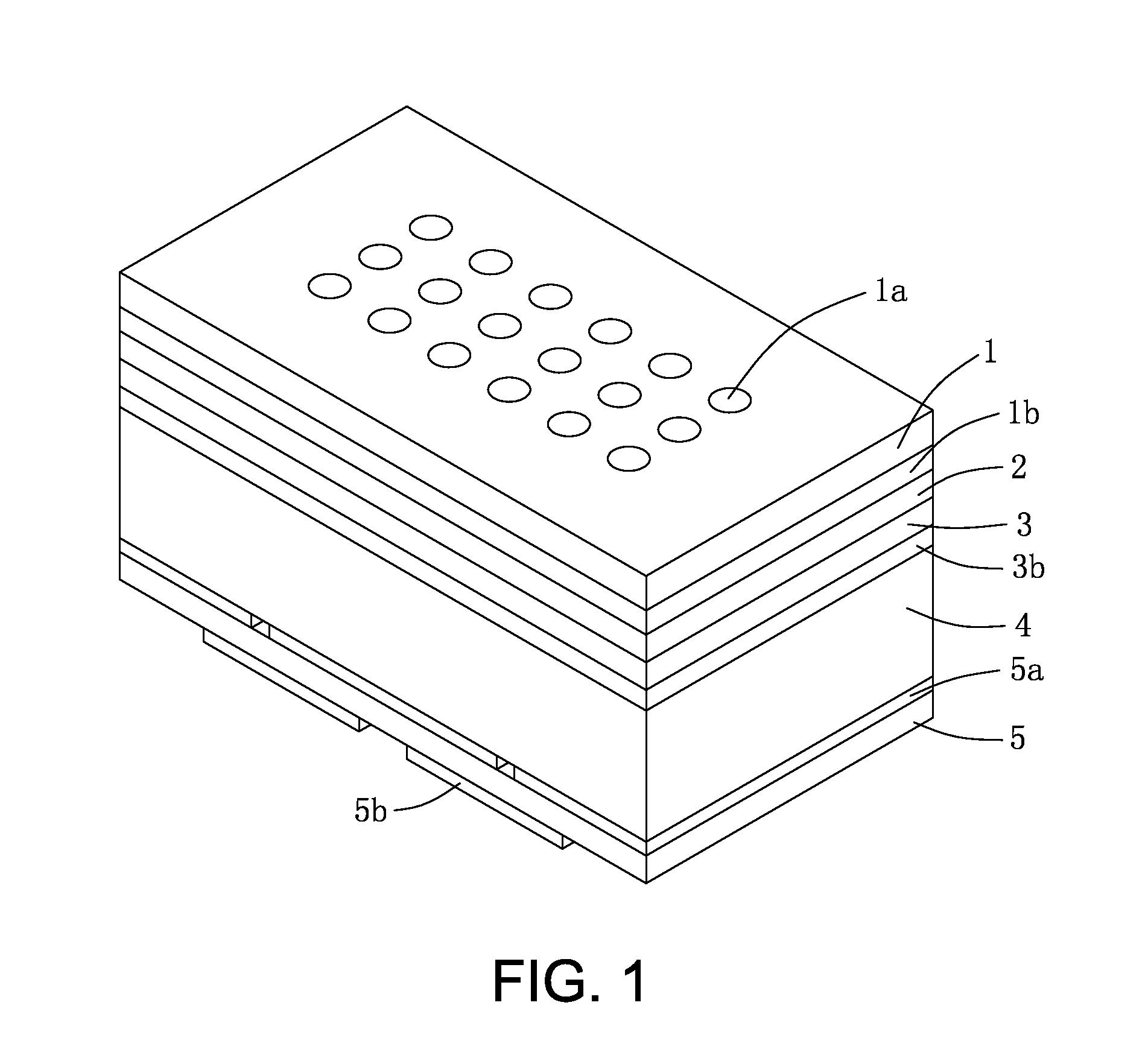
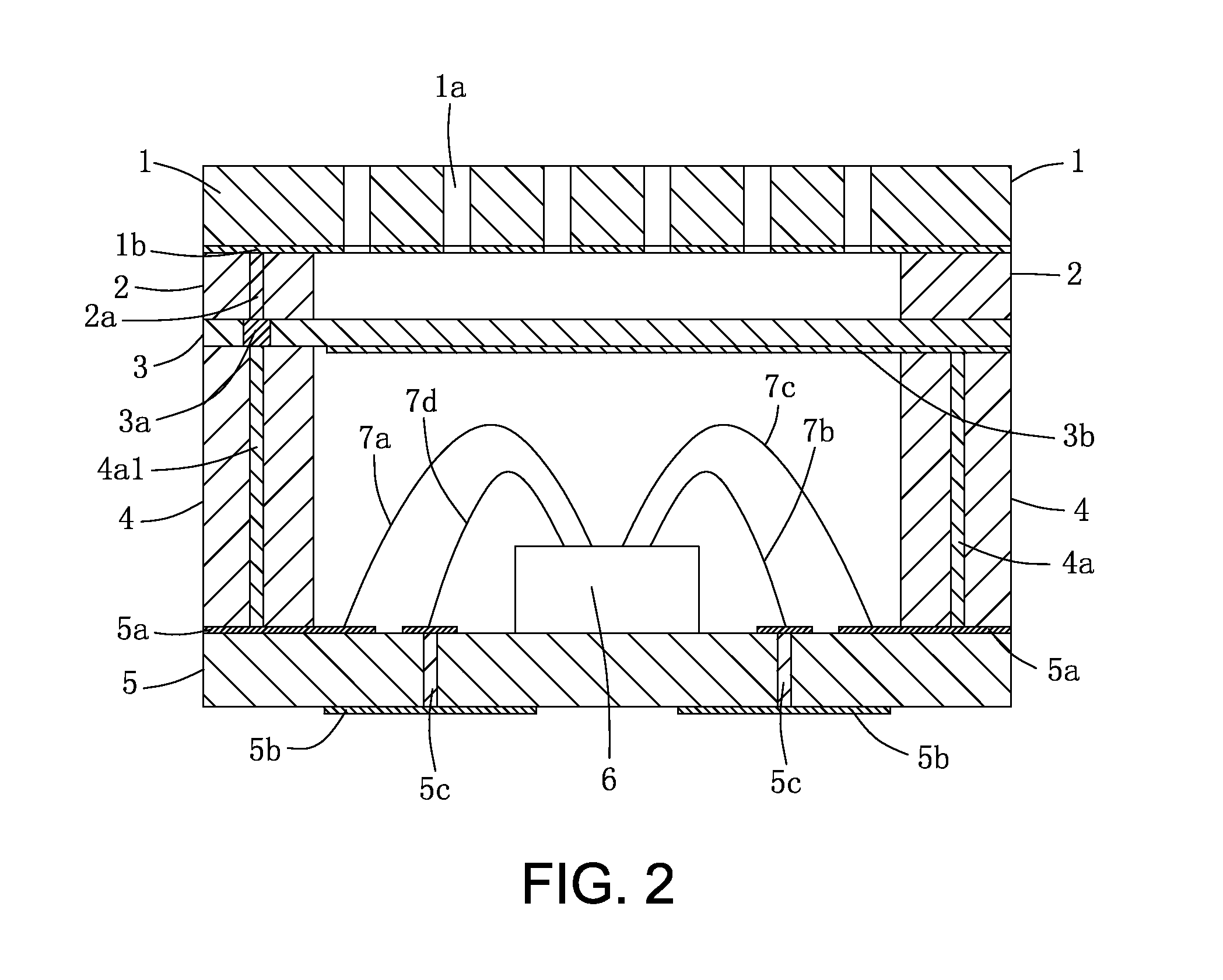
[0019]Referring to FIGS. 1 to 2, an electrostatic loudspeaker according to the first embodiment of the present invention is provided. The electrostatic loudspeaker has a backplate 1, a diaphragm 3, an insulator 2, an insulative spacer 4, a substrate 5, a plurality of metal wires 7 and a plurality of metal connection posts. The backplate 1, the insulative spacer 4 and the substrate 5 are mainly formed by insulative materials, such as FR-4, G10, BT. The backplate 1 opens a plurality of sound apertures 1a through which sound waves are radiated to exterior when the diaphragm 3 being driven to vibrate and sound. Further, the size, amount, shape and arrangement of the sound apertures 1a are determined depending on the acoustic characteristic requirements, for example, the sound apertures 1a can be shaped in round or rectangle.

[0020]The backplate 1 has the base material and a metal film 1b. The metal film 1b is formed on an inner surface of the backplate 1. The diaphrag...

second embodiment

The Second Embodiment

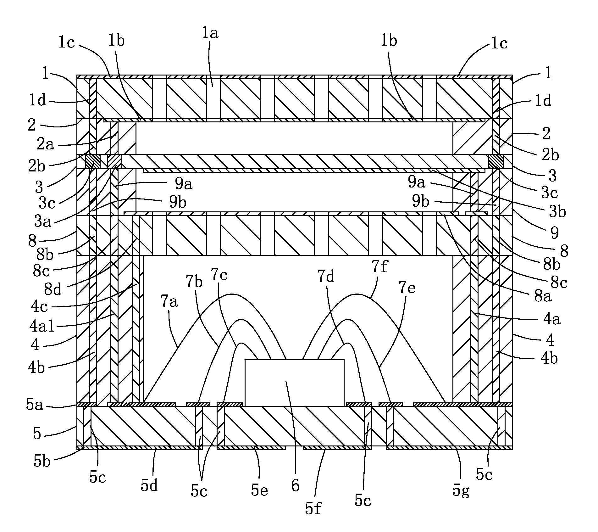
[0026]Referring to FIG. 3, another electrostatic loudspeaker according to the second embodiment of the present invention is disclosed. Comparing to the first embodiment of the present invention, the electrostatic loudspeaker of the second embodiment further has a shielding case to prevent connections paths from the electromagnetic interference.

[0027]The electrostatic loudspeaker has a backplate 1, a diaphragm 3, an insulator 2, a insulative spacer 4, a substrate 5, the shielding case, a plurality of metal wires 7 and a plurality of metal connection posts. The backplate 1, the insulative spacer 4 and the substrate 5 are mainly formed by insulative materials, such as FR-4, G10, BT. The backplate 1 opens a plurality of sound apertures 1a through which sound waves are radiated to exterior when the diaphragm 3 being driven to vibrate and sound. Further, the size, amount, shape and arrangement of the sound apertures 1a are determined depending on the acoustic characte...

third embodiment

The Third Embodiment

[0034]As shown in FIG. 4, another electrostatic loudspeaker according to the third embodiment of the present invention is disclosed. The electrostatic loudspeaker has a first backplate 1, a diaphragm 3, a first insulator 2, an insulative spacer 4, a substrate 5, and a driving circuit element 6, a plurality of metal wires 7, a second backplate 8, a second insulator 9, a shielding case, and a plurality of metal connection posts. It is noted that the first backplate 1 is the same as the backplate 1 in the first and second embodiments. Using the different term to indicate the same part is not intended to confuse the skilled person in this art, but conveniently describe the third embodiment of the present invention. The diaphragm 3 is sandwiched between the first backplate 1 and the second backplate 2. When the electrostatic loudspeaker working, the first backplate 1 and the second backplate 2 are applied inverse voltage so that they seldom adhesively contacts with th...


PUM


Abstract

An electrostatic loudspeaker includes a backplate having a metal film acting as one electrode of a capacitor and defining a number of sound apertures therein; a diaphragm insulatively spaced a distance from the backplate to form the capacitor; the diaphragm comprising a metal film acting as the other electrode of the capacitor; a back chamber having a substrate and an insulative spacer for joining edge portions of the diaphragm and the substrate; a driving circuit element for converting electrical signals from exterior input pads into driving signals to drive the diaphragm to vibrate and sound; the driving circuit element being mounted on an inner surface of the substrate and being accommodated in the back chamber; and a first, second and third connection paths for respectively electrically connecting the driving circuit element with the two electrodes of the capacitor, and the exterior input pads. An electrostatic loudspeaker with two backplates is also disclosed.

Description

BACKGROUND OF THE INVENTION[0001]1. Field of the Invention[0002]The present invention relates to an electroacoustic transducer, and more particularly relates to a small or miniature electrostastic loudspeaker (ESL).[0003]2. Description of Related Art[0004]Loudspeaker is an electroacoustic transducer for changing electrical signals into sound. The loudspeaker pushes a medium in accord with the pulsations of an electrical signal, thus causing sound waves to propagate to where they can then be received by the ear. According to the different physical effects of the electroacoustic conversion, the loudspeakers are divided into many kinds of types, such as magnetic loudspeaker, piezoelectric loudspeaker, electrostatic loudspeaker (condenser loudspeaker) and moving-coil loudspeaker (dynamic loudspeaker). Each type of the loudspeaker has advantages and disadvantages. In recent years, the moving-coil loudspeaker has been widely used because of the advantages in relatively great variety and m...

Claims


Application Information

Patent Timeline
Patent Type & Authority Applications(United States)
IPC IPC(8): H04R1/00
CPCH04R1/04H04R19/02H04R1/06
Inventor LI, GANGHU, WEIMEI, JIA XIN
Owner MEMSENSING MICROSYST SUZHOU CHINA
Learn More