Method of evaluating a reconstructed surface, corneal topographer and calibration method for a corneal topographer

a corneal topographer and reconstruction method technology, applied in the field of methods, can solve problems such as inaccuracy in reconstructing corneal surfaces, ambiguity in the relationship between stimulator source points and image points, and the procedure is not without problems

Inactive Publication Date: 2011-01-13
STICHTING VUMC
View PDF4 Cites 7 Cited by
  • Summary
  • Abstract
  • Description
  • Claims
  • Application Information

AI Technical Summary

Benefits of technology

[0006]Therefore, it is an object of the present invention to provide a method for evaluation of a reconstructed surface that enables to assess the relevance of the calculated difference between the actual (target) surface and the reconstructed surface in an easy manner. It is another object of the present invention to provide a corneal topographer that enables the evaluation of a reconstructed surface in an easy manner. It is a further object of the present invention to provide a calibration method for a corneal topographer.
[0013]By applying this method, the accuracy of the reconstructed surface can be assessed more easily because of the visualisation of the residual together with the image. By displaying the residual on the image target, one can also assess which parts of the reconstructed surface suffer from the largest error (or residual) and which parts have a small error. This may be important in case the accuracy requirement of the reconstructed surface is not uniform. As an example, reference can be made to the reconstruction of a corneal surface using a corneal topographer. In such an apparatus, a reconstruction of a corneal surface is determined (e.g. using a numerical algorithm), the reconstructed surface is further to be used in a subsequent surgical procedure to adjust a patients cornea e.g. by using laser technology. It will be clear to the skilled person that in order for this procedure to be successful, the accuracy of the reconstructed surface is important and should be verified. By visualising the reflected image of the target (e.g. the corneal surface), together with the residuals, the accuracy of the reconstructed surface can be assessed by visual inspection. This visual inspection may also be used to determine any further steps to be taken in e.g. modifying the reconstructed surface to reduce the discrepancy between the actual (target) surface and the reconstructed surface. Note that any method or device suitable can be applied for displaying the residual together with the reflected image. Both can e.g. be displayed on a screen that receives its input from a CCD camera, the camera serving as image target for receiving the reflected image from the target surface. Note that the image target can be any image (or picture) recording or receiving device such as a CCD camera or a video camera. The target surface in general represented the subject that is examined, in case the method is applied for examining a patients eye, the target surface can e.g. be the cornea of said eye.
[0029]A corneal topographer according to the present invention differs from conventional topographer in that it enables a.o. a residual calculated from a comparison between an actual surface (e.g. a corneal surface) and a reconstructed surface to be displayed together with the reflected image from the target surface. Both can e.g. be displayed together on a screen of the topographer. As described above, such visual inspection being readily available provides an easy way to assess the accuracy of the reconstruction, it may also be a useful tool in deciding whether or not an adjustment of the reconstructed surface is required or not.

Problems solved by technology

However, this procedure is not without problems.
This leads to inaccuracy in reconstructing corneal surfaces that are not rotationally symmetric.
This means that in Placido-based topography, there is ambiguity in the relationship between the stimulator source points and image points especially when the cornea is not a rotationally-symmetric surface.
A drawback of the proposed method is however that it does not provide an easy way to assess the relevance of the calculated difference between the actual (target) surface and the reconstructed surface.

Method used


Image

  • Method of evaluating a reconstructed surface, corneal topographer and calibration method for a corneal topographer
  • Method of evaluating a reconstructed surface, corneal topographer and calibration method for a corneal topographer
  • Method of evaluating a reconstructed surface, corneal topographer and calibration method for a corneal topographer

Examples


Embodiment Construction

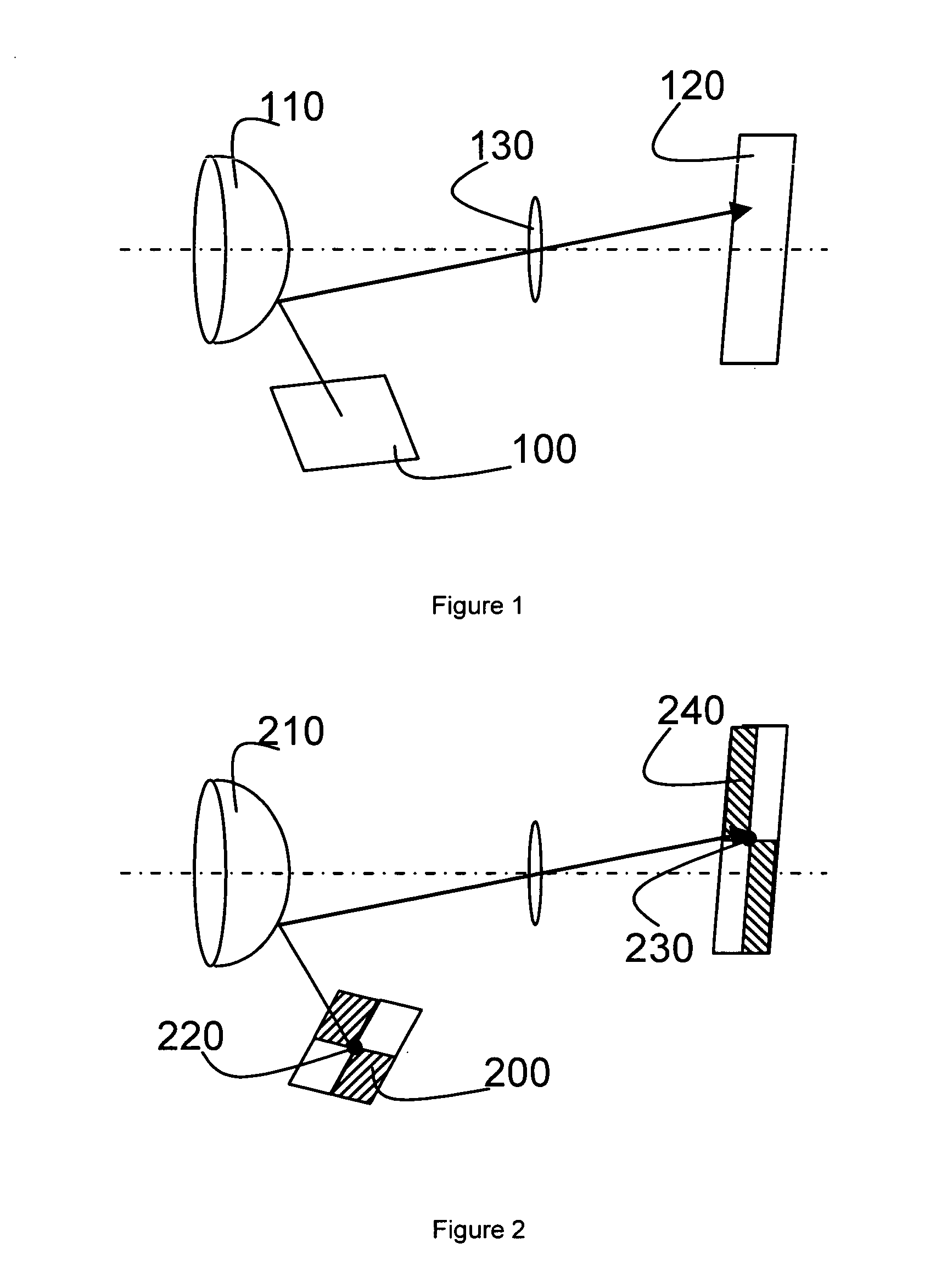
[0039]FIG. 1 schematically depicts a part of a stimulator source 100 arranged to illuminate a target surface 110 (the target can e.g. be an eye). The ray of light emanating from the stimulator source is reflected on the target surface, the reflected ray of light is received by the image target 120 which can e.g. be a CCD camera. Between the target surface and the image target, a lens 130 can be present.

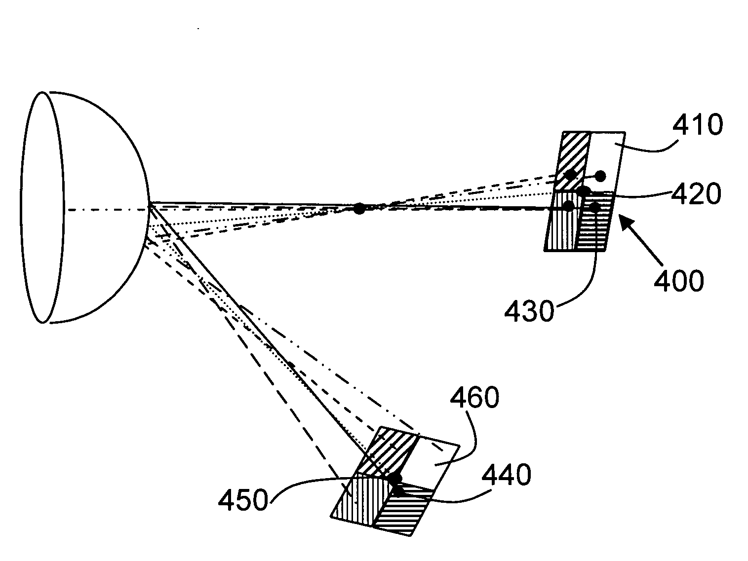
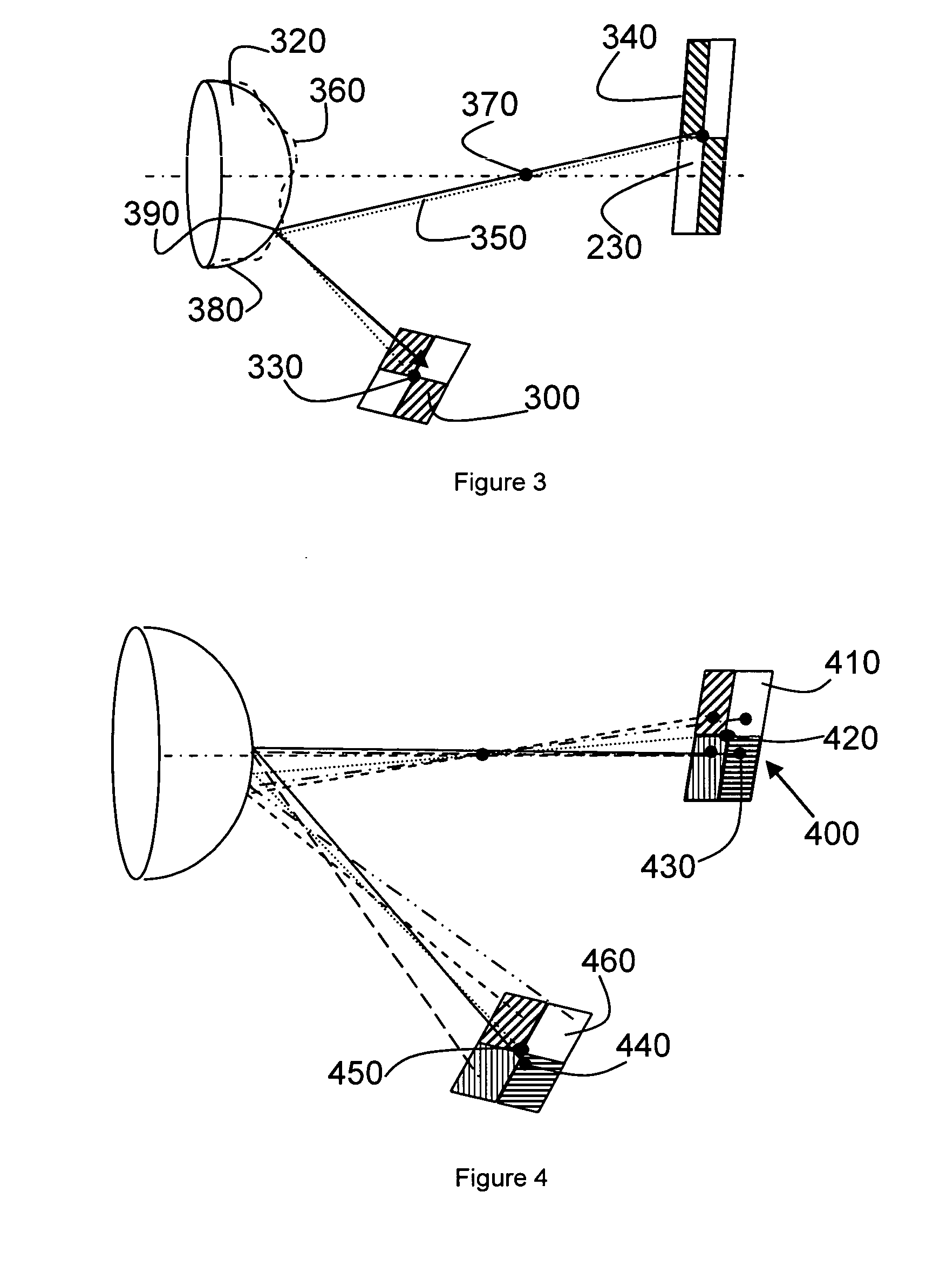
[0040]In general, when the stimulator source does not comprise distinct feature points, it is not possible to establish a one-to-one relationship between a point on the stimulator source and the corresponding projection on the image. FIG. 2 schematically depicts an arrangement that enables this correspondence. FIG. 2 schematically depicts a part of the stimulator source 200 arranged to illuminate a target surface 210. The part of the stimulator source 200 as shows comprises a pattern of rectangular shapes. The different parts or shapes of the stimulator source can e.g. emit a differen...


PUM


Abstract

A Method of evaluating a correspondence between a target surface and a reconstructed surface representing the target surface is described. The reconstructed surface can be constructed by processing information obtained by illuminating the target surface with a pattern of light of a stimulator source, and capturing a reflected image of the pattern of light on an image target, the method further comprising the steps of—Determine a reference image point on the image target corresponding to a reference stimulator point on the stimulator source,—Calculating for the reference image point, using the reconstructed surface, a residual representing the correspondence between the target surface and the reconstructed surface.—Displaying the residual together with the reflected image.

Description

CROSS-REFERENCE TO RELATED APPLICATIONS[0001]This application is the National Stage of International Application No. PCT / EP2007 / 009666, filed Nov. 2, 2007, the contents of which is incorporated by reference herein.FIELD OF THE INVENTION[0002]Corneal topographyBACKGROUND[0003]Measurement of the corneal shape is becoming a common procedure in ophthalmic practice. This is done by a technique called keratoscopy. This technique allows the study of the corneal image and the interpreted image distortions as an indication of an abnormal cornea topography. In keratoscopy the following elements are used: a stimulator source to illuminate a target surface (e.g. the cornea of an eye) with a pattern of light and an image target arranged to receive the reflection of the light pattern. The information from the reflection is used to reconstruct the corneal shape. One of the most commonly used stimulator sources is the Placido ring pattern consisting of a disk with alternating black and white rings....

Claims


Application Information

Patent Timeline
IPC IPC(8): G06K9/00H04N7/18
CPCA61B3/107G01B11/2513G01B11/25
Inventor DE PAZ SICAM, VICTOR ARNISNELLENBURG, JORIS-JOOSTVAN DER HEIJDE, GERRIT LUDOLPH
Owner STICHTING VUMC
Why Eureka
Try Eureka