Method to build 3D digital models of porous media using transmitted laser scanning confocal mircoscopy and multi-point statistics

a technology of laser scanning and mircoscopy, applied in the field of three-dimensional (3d) sample of porous media, can solve the problems of inability to image the tops and bottoms of grains and pores, limited penetration depth of lscm, unrealistic flow models, etc., and achieve the effect of reducing boundary effects inherent in grain size limitations and reducing limitations

Inactive Publication Date: 2011-01-06
SCHLUMBERGER TECH CORP
View PDF100 Cites 118 Cited by
  • Summary
  • Abstract
  • Description
  • Claims
  • Application Information

AI Technical Summary

Benefits of technology

[0036]According to embodiments of the invention, the invention includes a method for characterizing a three-dimensional (3D) sample of porous media to identify flow properties of the sample whereby one or more flow simulation model is generated from two or more set of transmitted measured data provided by at least one measuring tool in combination with at least one multi-point statistical (MPS) model. The method comprises: (a) retrieving the two or more set of transmitted measured data which includes data retrieved at two or more adjacent surfaces wherein each surface of the two or more adjacent surfaces can be at a different depth of the sample; (b) using at least one noise-reduction algorithm to identify noise data in the retrieved two or more set of transmitted measured data so that the identified noise data can be removed, such that the at least one noise-reduction algorithm includes a median-filtering algorithm; (c) selecting multiple depth-defined surface portions of the sample from the two or more set of transmitted measured data to create a training image so as to produce a 3D sample imaging log that can be communicated to the processor, and inputting the training image in the at least one MPS model; (d) performing the pattern-based simulations from the training image using a voxel-based template that is applied to the training image; and (e) constructing the at least one MPS model from the pattern-based simulations from the training image so as to build one or more complete-3D-sampling model of the sample such that the one or more complete-3D-sampling model provides for constructing one or more flow simulation model to assist in determining flow properties of the sample.
[0040]According to aspects of the invention, the invention includes the retrieved two or more set of transmitted measured data can be used to provide a training image to be used to assist in creating the at least one MPS model. A size and a shape of the at least one MPS model can be one of increased, modified or both from an original training image size and shape. The increased at least one MPS model size and shape can be one of a uniform geometric shape, a non-uniform geometric shape, or any combination thereof, so that the enlarged sizes and modified shapes reduce boundary effects so as to ensure for accurate flow modeling of the sample.
[0049]According to aspects of the invention, digital images of pore systems acquired by LSCM are directly used as training images, and MPS (Snesim algorithm) is used to generate larger realizations of the 3D pore systems. Such realizations are suitable for pore-network modeling and flow simulations, assuming that the measured pore systems are representative of a particular rock type. In some rocks, the pores may be too large for the LSCM technique. This occurs, for example, in thin sections where the average grain size is more than 15μ. This is because we want to see at least 2 grain diameters below the rock surface to generate true 3D images. Grain-size limitations can be reduced if the mineral material is eliminated, for example, by using acid to create pore casts. With pore casts, rocks with grain diameters up to 250μ can be imaged. The principle advantage of MPS can be that we can create enlarged models that reduce boundary effects inherent with smaller models when we run flow simulations.

Problems solved by technology

Depth of penetration of LSCM is limited because reflected light intensity is attenuated with depth.
An issue raised implicitly by current MPS algorithms is how to generate training images.
However, their flow models are unrealistic because they imaged thin slabs of rock, up to 200μ in thickness, such that they failed to image the tops and bottoms of grains and pores.
In other words, their grain sizes were too coarse for the LSCM technique, resulting in that they could not quantify true 3D pore geometry.
Because of this flawed assumption, their model does not capture rock heterogeneity, and does not depict true 3D pore geometry.

Method used


Image

  • Method to build 3D digital models of porous media using transmitted laser scanning confocal mircoscopy and multi-point statistics
  • Method to build 3D digital models of porous media using transmitted laser scanning confocal mircoscopy and multi-point statistics
  • Method to build 3D digital models of porous media using transmitted laser scanning confocal mircoscopy and multi-point statistics

Examples


Embodiment Construction

[0067]The particulars shown herein are by way of example and for purposes of illustrative discussion of the embodiments of the present invention only and are presented in the cause of providing what is believed to be the most useful and readily understood description of the principles and conceptual aspects of the present invention. In this regard, no attempt is made to show structural details of the present invention in more detail than is necessary for the fundamental understanding of the present invention, the description taken with the drawings making apparent to those skilled in the art how the several forms of the present invention may be embodied in practice. Further, like reference numbers and designations in the various drawings indicated like elements.

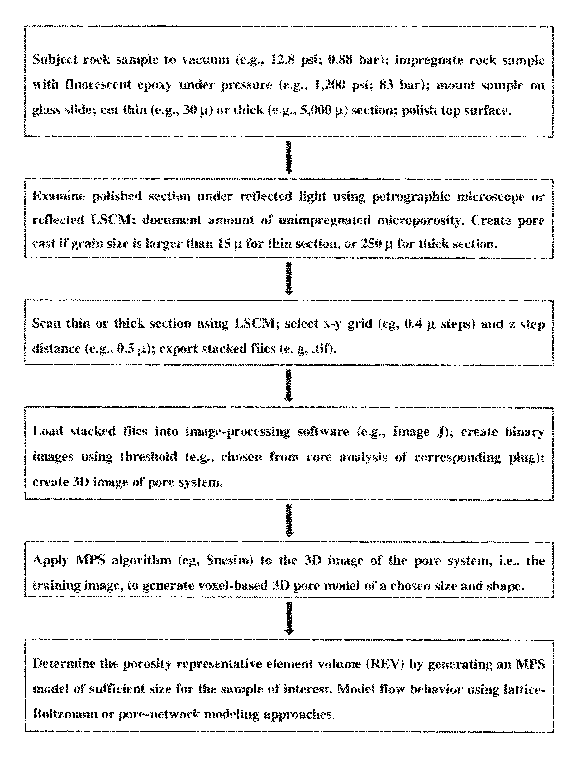
[0068]According to embodiments of the invention, the invention includes a method for characterizing a three-dimensional (3D) sample of porous media using at least one measuring tool that retrieves two or more set of transmitt...


PUM


Abstract

Methods for characterizing a three-dimensional (3D) sample of porous media using at least one measuring tool that retrieves two or more set of transmitted measured data at two or more depths of the sample, such that the retrieved two or more set of transmitted measured data is communicated to a processor and computed in at least one multi-point statistical (MPS) model.

Description

BACKGROUND OF THE INVENTION[0001]1. Field of the Invention[0002]The present invention generally relates to methods for characterizing a three-dimensional (3D) sample of porous media. In particular, a method using at least one measuring tool that retrieves two or more set of transmitted measured data at two or more depths of the sample, such that the retrieved two or more set of transmitted measured data is communicated to a processor and computed in at least one multi-point statistical (MPS) model so as to characterize the three-dimensional (3D) sample of porous media.[0003]2. Background of the Invention[0004]Confocal microscopy can be defined as a technique for obtaining high resolution images and three dimensional (3-D) reconstructions of biological specimens; a laser light beam is expanded to make optimal use of the optics in the objective lens and is turned into a scanning beam via an x-y deflection mechanism and is focused to a small spot by the objective lens onto a fluorescen...

Claims


Application Information

Patent Timeline
IPC IPC(8): G06G7/57G06F17/50G06K9/00G06F17/18
CPCG06T17/00G02B21/0024
Inventor HURLEY, NEIL FRANCISZHANG, TUANFENGZHAO, WEISHUXU, GUANGPING
Owner SCHLUMBERGER TECH CORP
Why Eureka
Try Eureka