
Rear-Projection Screen

a rear-projection screen and screen technology, applied in the field of rear-projection screens, can solve the problems of low or no effective gain in image quality, one or more other screen characteristics often degrade, and the display applications intended to be viewable on the windows from both the interior and exterior of the building are particularly challenging to manufacturers, so as to achieve little and improve image contrast

Active Publication Date: 2011-01-06
AVERY DENNISON CORP
View PDF32 Cites 28 Cited by
  • Summary
  • Abstract
  • Description
  • Claims
  • Application Information

AI Technical Summary

Benefits of technology

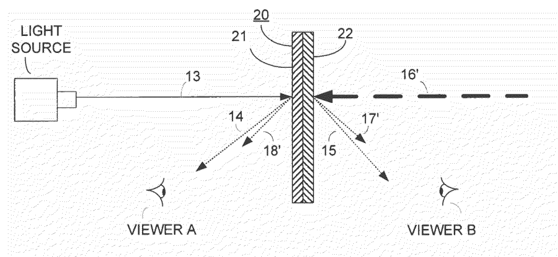
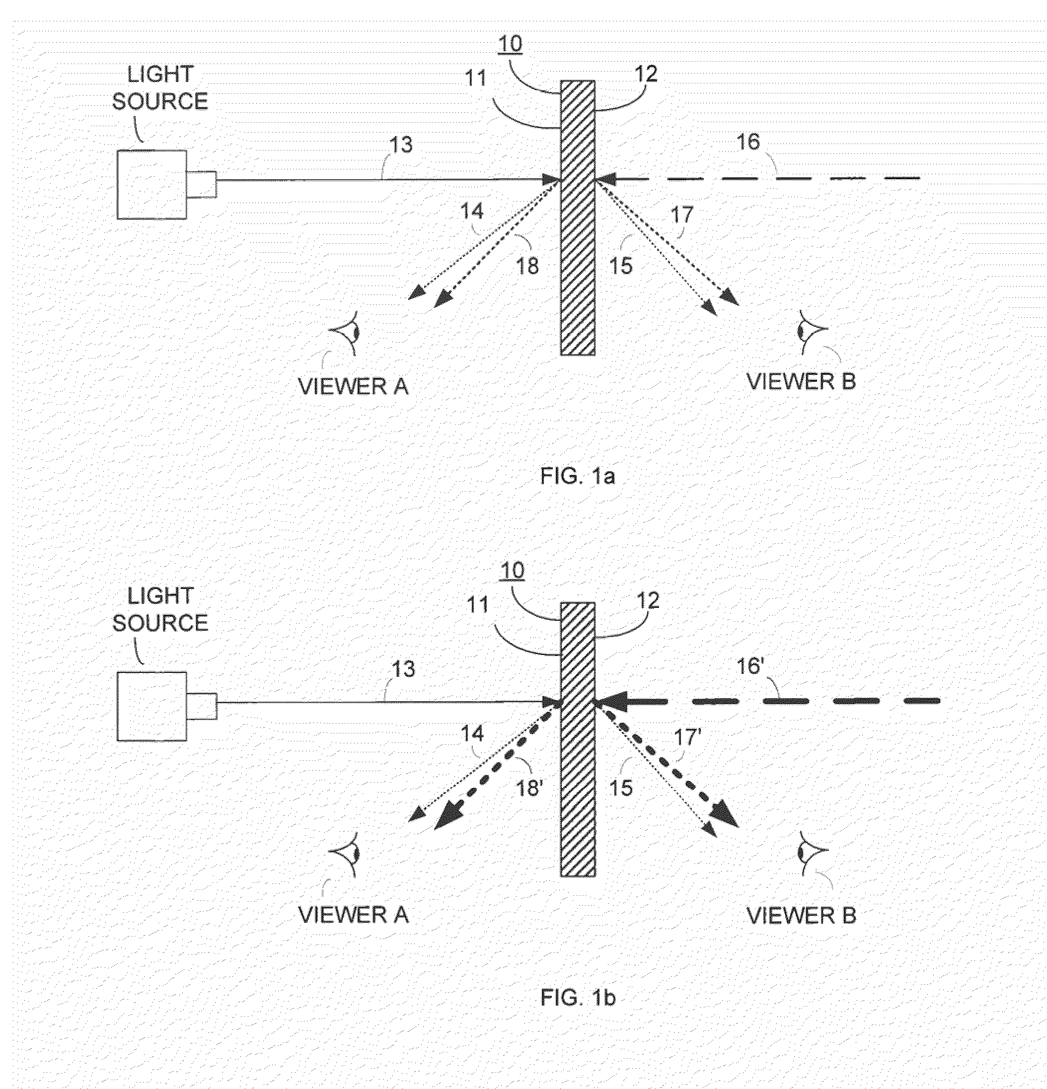
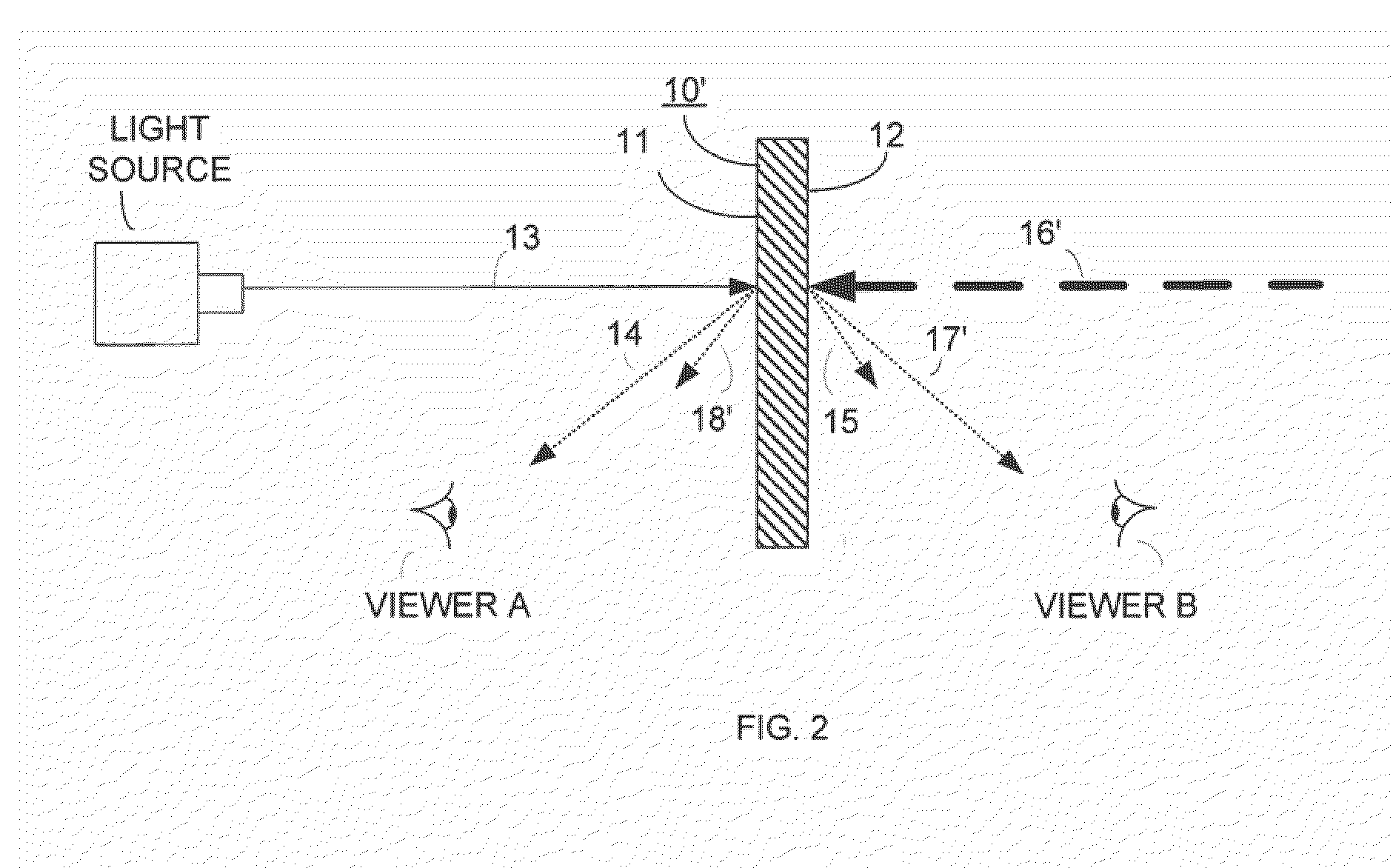
[0004]The primary object of the invention is to provide a rear-projection screen having improved image contrast and very little, if any, reflection of sunlight to a viewer located outside of a building. It has been discovered that a rear-projection screen having a visible light transmittance of between 25 to 50% and visible light absorbance of between 35 to 55% would exhibit the desired image contrast.
[0006]Still another object of the invention is to provide a rear-projection screen having improved image contrast and enhanced image brightness which is be easily and temporarily or permanently mountable onto a transparent substrate such as a store window for viewing of a projected image inside and outside of a building.

Problems solved by technology

Unfortunately, as one screen characteristic is improved, one or more other screen characteristics often degrade.
As a result, there is little or no effective gain in the image quality.
Display applications intended to be viewable on a window from both the interior and exterior of a building are particularly challenging to manufacturers since that the relative amount of sunlight reflected from the window is much greater than the ambient light reflected inside of the building.

Method used


Image

  • Rear-Projection Screen
  • Rear-Projection Screen
  • Rear-Projection Screen

Examples


example 1

[0071]Example 1 included a light-diffusive film and a light-absorptive film similar to the laminate described in FIG. 3. The light-diffusive film was identical to that described for Comparative Example 1. The light-absorptive film was a transparent monolayer film having a matrix of amorphous polyethylene terephthalate and about 0.2% by weight relative to the entire weight of the film of carbon black incorporated therein. The light-diffusive and light-absorptive films were adhesively laminated together by use of a transparent acrylic pressure sensitive adhesive to form a two-ply laminate.

example 2

[0072]Example 2 was similar to Example 1, except that an extra light-absorptive film having an identical composition as that described in Example 1 was added. The light-diffusive and light-absorptive films were fused together by heat and pressure form a three-ply laminate.

example 3

[0073]Example 3 was similar to Example 2, except that an extra light-absorptive film having an identical composition as that described in Example 1 was added. The light-diffusive film and light-absorptive films were fused together by heat and pressure form a four-ply laminate.


PUM

PropertyMeasurementUnit
Fractionaaaaaaaaaa
Fractionaaaaaaaaaa
Fractionaaaaaaaaaa

Abstract

The present invention is directed to a rear-projection screen which encompasses 1) a flexible light-diffusive first film having a substantially smooth first surface and an opposing substantially smooth second surface, and comprising a wax-free amorphous thermoplastic matrix having a plurality of light-diffusing particles dispersed therein and which is lens-free; and 2) an opposing flexible light-absorption second film having a first surface and an opposing second surface, and comprising a thermoplastic matrix having a plurality of light-absorbing particles dispersed therein, wherein the first and second films are adapted to be 3) bonded together in direct contact with each other and then, affixed as a laminate to one or more transparent rigid substrates or 4) affixed individually to a transparent rigid substrate.

Description

TECHNICAL FIELD[0001]This invention relates to a rear-projection screen and in particular a rear-projection screen having at least two layers which enhances the image-contrast of a projected image and reduces the effect of ambient light.BACKGROUND OF THE INVENTION[0002]Rear-projection screens are utilized for various applications, such as, for example, advertising in store windows, show rooms, exhibitions, shopping malls, lobbies, restaurants, museums and various transportation stations. In such applications, an image source located behind the screen projects image light forward along a projection axis toward the screen to form a visible image at the plane of the screen which is distributed to viewers on both the receiving or rear side of the screen and the opposing, front side of the screen. Typical screen characteristics used to describe a screen's performance include contrast, image brightness, visible light transmittance, visible light absorbance and visible light reflectance.[0...

Claims


Application Information

Patent Timeline
IPC IPC(8): G03B21/62B32B37/00
CPCY10T156/10G03B21/60
Inventor PEROTTI, DANIELSIRAUX, GUY
Owner AVERY DENNISON CORP
Learn More