
Floating front-end amplifier and one-wire measuring devices

a technology of front-end amplifier and measuring device, which is applied in the direction of amplifiers, positive-feedback-circuit arrangements, and reradiation, etc., can solve the problem of high impedan

Active Publication Date: 2011-01-06
CSEM CENT SUISSE DELECTRONIQUE & DE MICROTECHNIQUE SA RECH & DEV
View PDF9 Cites 23 Cited by
  • Summary
  • Abstract
  • Description
  • Claims
  • Application Information

AI Technical Summary

Benefits of technology

[0026]It is also important to shield the input line of the floating front-end amplifier by the internal ground potential or, even better, by the follower output. Doing so will drastically reduce the effect of any stray capacitance or impedance, thus leading to outstanding high impedance.
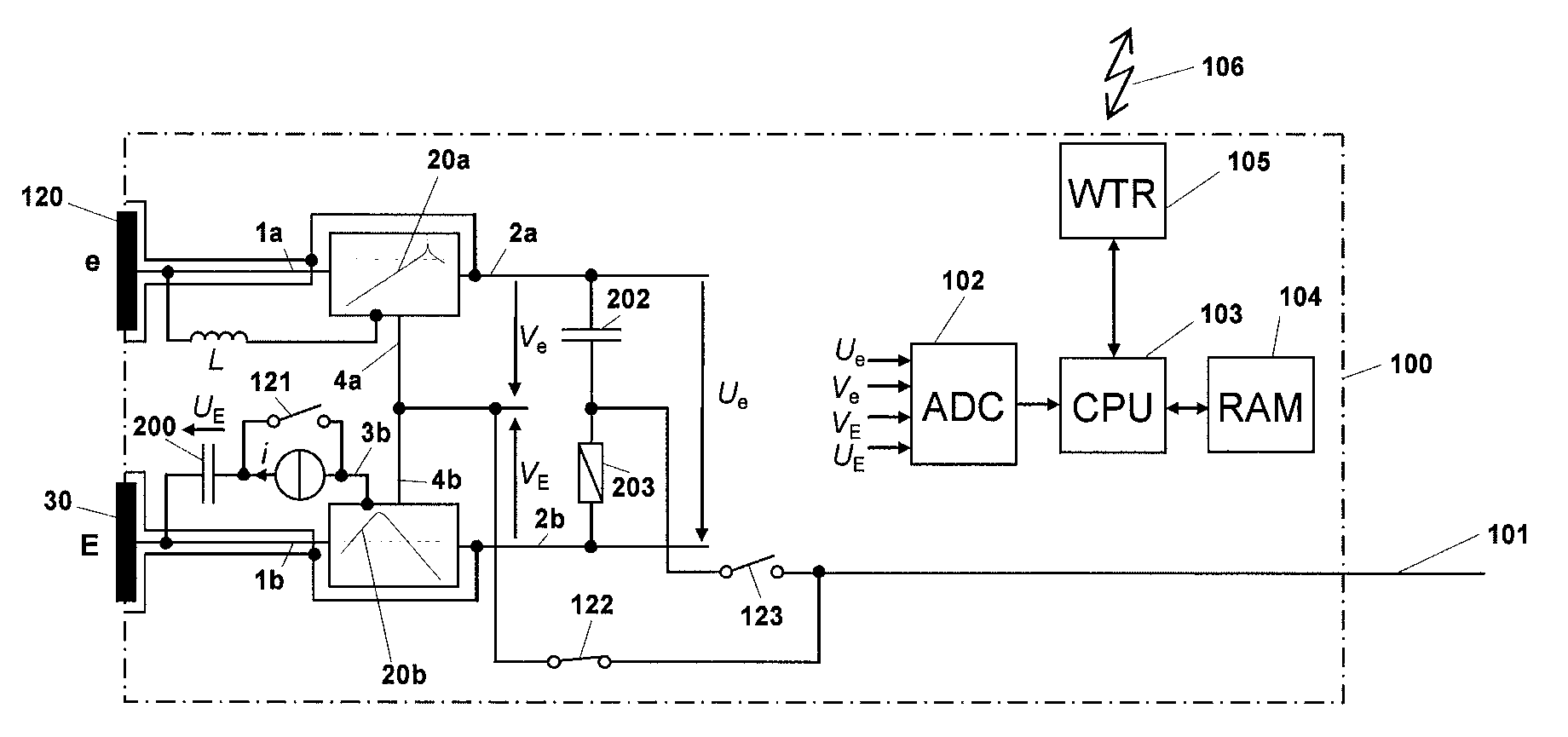
[0031]The reference unit, thanks to the use of a floating front-end amplifier with its input connected to a so-called reference electrode and its external ground connected to a so-called guard electrode, make sure that the potential of the external wire connecting the units is the same than the one inside the body (below the reference electrode). This has several significant advantages.
[0035]Fourth, as there is only one external wire, there is no risk of crosstalk between wires.
[0038]For impedance measurements and for this voltage to be to different from zero, an additional so-called injection electrode is needed for at least one of the measuring units. In addition, there must be in the measuring units with an injection electrode a current source or other means to circulate a current through the injection electrode, the body, the guard electrode of the reference unit and back by the external wire. When the current source is not set to zero, a current will flow through the body and a voltage drop (between the impedance electrode and the external wire) will be measured by all measuring units. The current source may, for example, produce an alternative current with constant magnitude and frequency outside the bandwidth of any biopotential, so that there would be an easy way to extract and separate the voltage components originating from bioelectric activity and from the current injection.
[0042]The measuring units can also benefit from the outstanding performance brought by the floating front-end amplifier in terms of input impedance and unity gain. In one embodiment, the input of the floating front-end amplifier is connected to the biopotential / impedance electrode and its external ground to the external wire. For measuring units with a current injection electrode, one terminal of the current source is connected to this electrode and the other to the external ground of the floating front-end amplifier.

Problems solved by technology

Doing so will drastically reduce the effect of any stray capacitance or impedance, thus leading to outstanding high impedance.Any amplifier has a polarization current which has to be conducted to ground.

Method used


Image

  • Floating front-end amplifier and one-wire measuring devices
  • Floating front-end amplifier and one-wire measuring devices
  • Floating front-end amplifier and one-wire measuring devices

Examples


Embodiment Construction

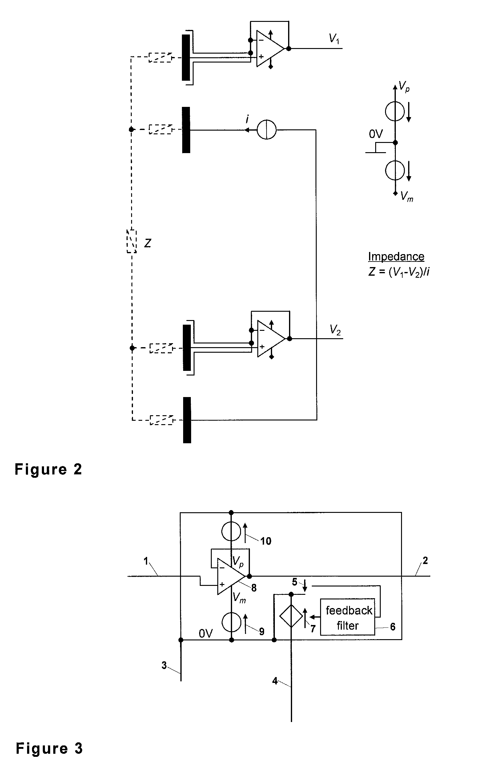
[0076]FIGS. 1 and 2 have been described above. The same reference numerals will now be used for same parts or the like.

[0077]FIG. 3 shows an embodiment of a floating front-end amplifier, according to the present invention. The input (1) connected to the follower amplifier (8) features very high input impedance, while the output (2) features low output impedance. The potential of the output (2) equals the potential of the input (1) with great accuracy. The potential of the internal ground (3) is actively controlled to the same potential of the input (1).

[0078]The voltage (5) between the output (2) and the internal ground (3) can actually be seen as the error signal feeding the controller (6) (or feedback filter) which determines the control voltage (7) so that the potential of the internal ground (3) equals the potential of the input (1) whatever is the potential of the external ground (4).

[0079]The potential of the internal ground (3) is also the common to potential of the power sup...


PUM


Abstract

A follower amplifier with power supply biased by a controlled voltage source such that the power supply potentials are, for the frequencies of interest, as close as possible to the potential of the follower output. There is proposed a front-end electronic circuit for biopotential and impedance measurements with outstanding performances (very high input impedance and gain very close to unity). Preferably, the explicit guard electrode and the explicit electronic unit at the belt are no longer necessary; all electronics is embedded in units placed directly at the measurement sites. Moreover, the proposed front-end electronic circuit allows a drastic simplification of the cabling and connectors since all units are connected to only one wire (the theoretical minimum) for potential reference and current return. Preferably, this wire does not even require an electrical isolation and can be easily embedded in the textile of a shirt, in a garment, mesh, belt, etc.

Description

FIELD OF THE INVENTION[0001]The present invention relates to a floating front-end amplifier and to one-wire measuring devices.BACKGROUND OF THE INVENTION[0002]One-wire measuring devices may be used especially in the field of monitoring vital signs and parameters from biopotentials (e.g. ECG) or / and from impedance measurements (e.g. respiration).[0003]Biopotentials provide information on some electrical physiological process of the human or animal body. Electrodes are used at the interface of the measuring device and the body. Usually, the electrodes are applied on the skin, but they can be elsewhere. They can also be needle electrodes inserted in the body.[0004]The interface between the body and the electrodes is generally a chemical cell that translates ionic current into metallic current. A gel is usually used between the electrodes and the body in order to decrease the contact impedance and consequently the noise and motion artefacts. However, some measuring devices use dry elect...

Claims


Application Information

Patent Timeline
IPC IPC(8): G01R27/08H03F1/00A61B5/308
CPCA61B5/04004H03F3/45475A61B5/0428A61B5/30A61B5/305
Inventor CHETELAT, OLIVIERSOLA I CAROS, JOSEP
Owner CSEM CENT SUISSE DELECTRONIQUE & DE MICROTECHNIQUE SA RECH & DEV
Learn More