
LED packages with scattering particle regions

a technology of scattering particle and led package, which is applied in the direction of basic electric elements, semiconductor devices, electrical equipment, etc., can solve the problems of significant variation in the package, the predominance of converted light emitted sideways into high viewing angles, and the inability of conventional leds to generate white light from their active layers. achieve the effect of improving uniformity

Active Publication Date: 2011-01-06
CREELED INC
View PDF89 Cites 85 Cited by
  • Summary
  • Abstract
  • Description
  • Claims
  • Application Information

AI Technical Summary

Benefits of technology

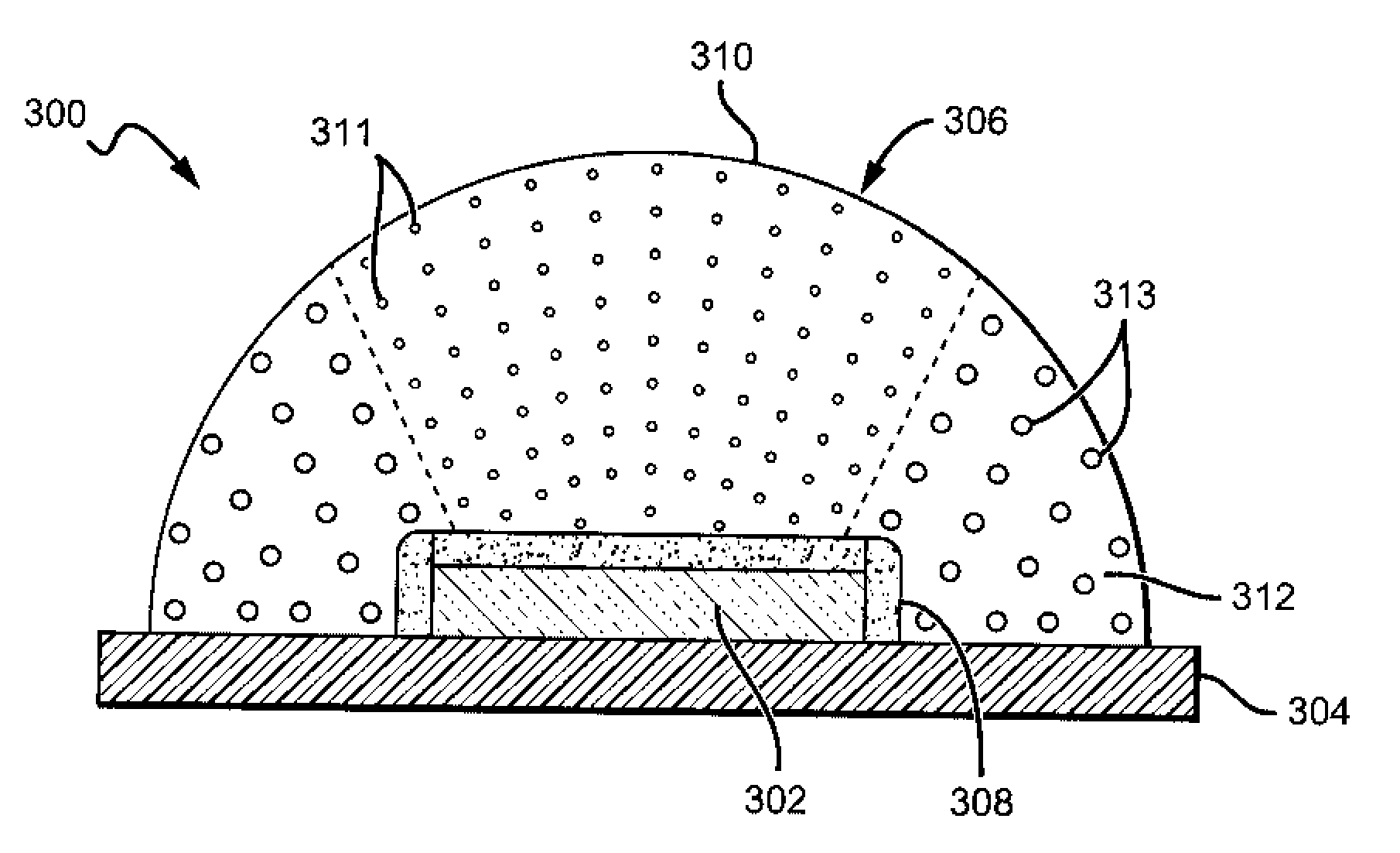
[0015]The present invention is directed to emitter packages having scattering particles engineered to scatter target wavelengths or wavelength ranges of light from an emitter based on the emission profile of the emitter. The scattering particles are arranged to mix the light from the emitter so that the emitter package provides a more uniform light when viewed at different viewing angles. The present invention can be used in LED packages, and can provide different scattering particles in various regions around the LED to scatter target wavelengths of light emitting from the LED at a particular emission angles. This arrangement also provides for mixing of the LED light while minimizing the emission efficiency losses resulting from the scattering.
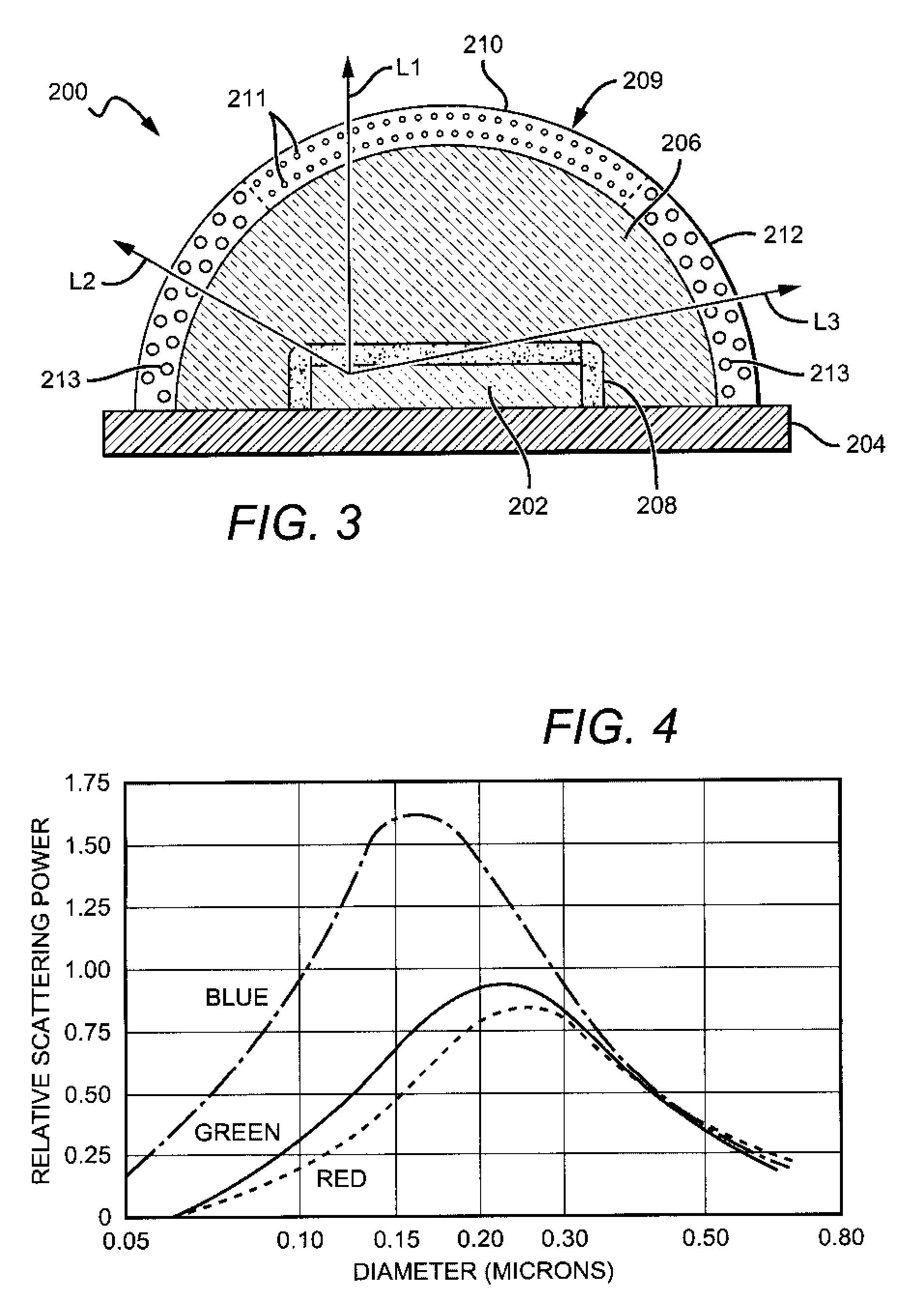
[0016]One embodiment of an LED package according to the present invention comprises at least one LED that emits LED light in an LED emission profile. The LED package also includes a first plurality of scattering particles to scatter a first target wavelength and a second plurality of scattering particles to scatter a second target wavelength that is different from the first target wavelength. The first and second scattering particles are arranged around the LED to scatter the LED light to improve the uniformity of the emission profile while minimizing the light loss.
[0017]Another embodiment of an emitter package, according to the present invention comprises at least one emitter that emits light in an emitter emission profile. It also includes a first region of first scattering particles and a second region of second scattering particles. The first and second regions are arranged around the at least one emitter to improve the emission uniformity of the emitter package compared to the emission profile of the emitter emission profile.
[0019]Still another embodiment of an LED package according to the present invention comprises at least one LED that emits light in an LED emission profile. The package also includes first and second scattering features, wherein the first scattering feature scatters a first target wavelength of light and the second scattering feature scatters a second target wavelength. Each of the first and second scattering features is arranged around the LED to scatter light from the LED based on the LED emission profile such that the LED package emits a package emission profile having improved uniformity compared to the LED emission profile.

Problems solved by technology

However, conventional LEDs cannot generate white light from their active layers.
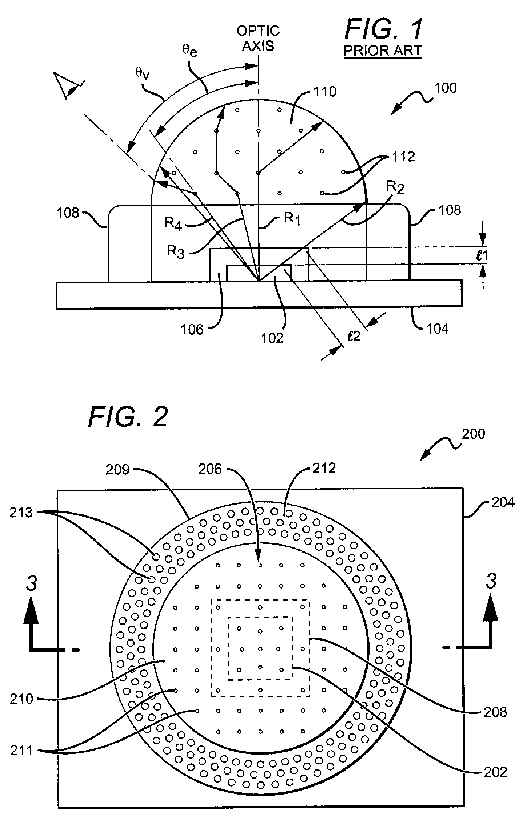
This packaging, however, can result in an LED package having significant variation of the color temperature of emitted light at different viewing angles with respect to the package.
This problem can be made worse in packages where the phosphor containing matrix material extends above the “rim” of the cup in which the LED resides, resulting in a predominance of converted light emitted sideways into high viewing angles (e.g., at 90 degrees from the optic axis).
The result is that the white light emitted by the LED package becomes non-uniform and can have bands or patches of light having different colors or intensities.
However, the color uniformity still suffers from phosphor concentration or phosphor thickness variations and differences in path length.
Without light scattering particles, the emission spectrum can exhibit a non-uniform emission pattern, producing a emission with variances in color temperature and intensity often noticeable to the human eye.
Such non-uniformities can render a light emitting device undesirable for certain applications.
Light scattering particles, however, can also reduce the LED package's emission efficiency.
This can result in unnecessary backscattering and absorption of the light that need not be scattered, which can result in unacceptable losses in emission efficiency.

Method used


Image

  • LED packages with scattering particle regions
  • LED packages with scattering particle regions
  • LED packages with scattering particle regions

Examples


Embodiment Construction

[0028]The present invention provides emitter packages exhibiting improved color emission uniformity and improved spatial color mixing for both single and multi-emitter packages. The embodiments are particularly well suited to packages using light emitting diodes (LED or LEDs) as their emitters, with many packages using white light emitting diodes (LEDs) or using multi-colored LEDs that emit a white light combination. The LED packages can comprise scattering particles arranged in different ways around the LED to scatter target wavelengths or wavelength ranges (“target wavelength”) of light based on the emission profile of the LED so that the LED package provides a more uniform light at different viewing angles.

[0029]As described in more detail below, for LED packages having white light emitting LEDs comprising a blue LED covered by yellow phosphor, the white light correlated color temperature (CCT) is typically higher near the normal emission angle (defined as 0 degrees with respect ...


PUM


Abstract

An LED package comprises at least one LED that emits LED light in an LED emission profile. The LED package includes regions of scattering particles with the different regions scattering light primarily at a target wavelength or primarily within a target wavelength range. The location of the regions and scattering properties are based at least partially on the LED emission profile. The regions scatter their target wavelength of LED light to improve the uniformity of the LED emission profile so that the LED package emits a more uniform profile compared to the LED emission profile. By targeting particular wavelengths for scattering, the emission efficiency losses are reduced.

Description

BACKGROUND OF THE INVENTION[0001]1. Field of the Invention[0002]The invention relates to light emitting devices (LED) packages and, more particularly, to white LED and multiple LED packages with scattering particles.[0003]2. Description of the Related Art[0004]Light emitting diodes (LED or LEDs) are solid state devices that convert electric energy to light, and generally comprise one or more active layers of semiconductor material sandwiched between oppositely doped layers. Typically, wire bonds are used to apply a bias across the doped layers, injecting holes and electrons into the active layer where they recombine to generate light. Light is emitted from the active layer and from all surfaces of the LED. A typical high efficiency LED comprises an LED chip mounted to an LED package and encapsulated by a transparent medium. The efficient extraction of light from LEDs is a major concern in the fabrication of high efficiency LEDs.[0005]LEDs can be fabricated to emit light in various c...

Claims


Application Information

Patent Timeline
IPC IPC(8): H01L33/00
CPCH01L33/44H01L33/50H01L33/56H01L33/58H01L2924/0002H01L2933/0091H01L2924/00
Inventor LE TOQUIN, RONAN
Owner CREELED INC
Learn More