Drip And Bubbler Irrigation Fertilizing System

Inactive Publication Date: 2011-01-06
ROIDE PAUL ANTHONY
View PDF5 Cites 5 Cited by
  • Summary
  • Abstract
  • Description
  • Claims
  • Application Information

AI Technical Summary

Benefits of technology

[0009]The invention involves three distinct embodiments. The first allows connection directly to a drip button emitter's output via plastic tubing and is composed of a mesh material sewn in the shape of a small pouch with a seam at the sides and end and attached to a plastic nipple at the opposite end. The pouch holds fertilizer pellets within and as water enters the pouch through the nipple end it disperses over and through the fertilizer pellets, thereby absorbing the fertilizer medium through a slow release process and then exits the pouch through the mesh material which surrounds it. The exiting water, enhanced by the fertilizer medium, is then absorbed into the ground around the plant. Soon after the drip cycle ends, the fertilizer medium, being open to air by means of the mesh that surrounds it, is able to aerate and dry, preserving itself for the next watering cycle. The fertilizer medium is made to last for a 6-36 month period, depending on the size of the pouch and quantity of fertilizing medium involved and can be replaced easily and effectively, allowing for use of different fertilizers for specific plants and growing seasons. This embodiment also contains a means to prevent chemical backflow from entering the water supply system by means of a plastic nipple that is angled downward from level toward the fertilizing pouch. Even if the pouch and emitter placed flat on the ground, the nipple will prevent any water chemically enhanced within the pouch from flowing upward back into the drip emitter. Another means of preventing backflow with upright (staked) drip emitters is by use of a tube clip that keeps the pouch below the top of the emitter keeping fertilized water from entering the emitter or water source.
[0011]The third embodiment of this design is again one that is circular like that of embodiment two but smaller in size and made to fit underneath standard upright or vertical drip emitter anchors used with adjustable flow emitters, micro bubblers and micro sprinklers. The closed pouch design forms a circle and can be slipped underneath the upright drip tube as they are inserted into the ground and will become wetted by the drip emitter run off and allow the chemicals within the pouch to be absorbed by the run off and applied directly to the plant within the drip emitter range. Each embodiment is designed to fit with a specific type of application but each design employs the same porous and flexible pouch material containing chemical inserts and relies upon the same methods to apply fertilizer in each drip application. The pouch is designed of flexible material and will stretch to fit over a standard size bubbler head or stretch to fit around a upright drip anchor as is it inserted in the field. The present invention thus provides a very cost effective way for growers and landscapers to fertilize with very low associated maintenance and in conjunction with their existing drip irrigation system. It allows for easy installation, maintenance and replacement and can be made into a variety of fertilizing specifications desired by the grower at any time. For example, the grower may specify a certain fertilizing formula during early plant growth and want to vary that formula as the plant matures and needs others nutrients for pollination or flower / fruit growth. The grower can meet this change simply by replacing the pouches on the targeted plants of concern with another desired fertilizing mix, while leaving the previous blend in place for less mature plants. The present invention allows then for multiple fertilizing blends to be applied within the same system at different points by targeting each individual fertilizing pouch. The pouches are easy to change and do not degrade over time. In addition, the present invention enhances the drip irrigation system by fully draining the emitters on the completion of each watering cycle and by closing off the emitters to outside air and the harmful effects of oxidizing water, which tends to clog the small emitter tolerances and parts within a standard drip emitter.

Problems solved by technology

They are physically complicated, must be plumbed into the system and remain a permanent part of the system, and must be maintained as a function of the watering rate.
Waterborne systems offer the advantages of instant and concentrated fertilizing, but are expensive and difficult to use in a manner that allows for gradual, long term continuous feeding within the irrigation system.
Complex timing controls are needed on the injecting fertilizing unit to time the controlled release of fertilizers, further adding to the cost and complexity of the system.
Therefore, most water borne fertilizer distribution is a very expensive and complicated process and is used mainly on large sprinkler type applications such as parks and golf courses or in large commercial environments.
Dry fertilizing applicators suffer the physical problems of positioning the pellets or powder widely and evenly around the target plants, while avoiding the effects of wind, rain, and runoff and of physical displacement from workers, animals or machinery to stay in the target area and deliver its nutrients.
Over time and exposure to water and air they lose some of their fertilizing potency, especially if they are unable to dry out between watering cycles.
Over wetting of the pellet type fertilizer causes it to dissolve and be applied too rapidly to the soil causing irregular and short term nutrient delivery.
This is another problem in many dry fertilizer irrigation delivery systems, one that need to be watched carefully.
None of the dry fertilizing systems now in use were designed for low volume, high efficiency drip irrigation systems which typically require liquid fertilizing systems if they fertilized at all.
Liquid fertilizing systems present a problem to most drip irrigation systems because the dissolved solids of the fertilizers tend to clog the emitter ports.
Even normal tap water having high mineral (hard water) content tends to clog emitters making their replacement more regular and adding expense to the irrigation maintenance program.
These systems are not suited well to low volume, high efficiency systems like drip irrigation because they tend to clog the drip elements and are not effectively absorbed into the soil in small areas due to the concentration of fertilizer content.
This system is ineffective in use because using a tablet in this manner will impede the natural flow of the drip emitter until it is somewhat dissolved, as the tablet itself contains no holes, only the surrounding jacket.
Unless the tablet is very porous in nature water will not easily flow through it until it has dissolved to some degree and it would seem to present a problem as it softened and clogged the housing.
The tablet inside such a housing would not receive enough air between watering to allow the fertilizing chemicals to dry out and therefore the tablet would become soft and disperse fertilizer too rapidly if soft or not rapid enough (or at all) if clogged within the enclosure.
It would also seem to be complex to manufacture and difficult to keep dirt and foreign materials from entering the drain holes, another potential source of water stoppage.
Finally, it is difficult to use in the field since there is no way to tell when the tablet has dissolved and the device needs to be replaced.

Method used


Image

  • Drip And Bubbler Irrigation Fertilizing System
  • Drip And Bubbler Irrigation Fertilizing System
  • Drip And Bubbler Irrigation Fertilizing System

Examples


Embodiment Construction

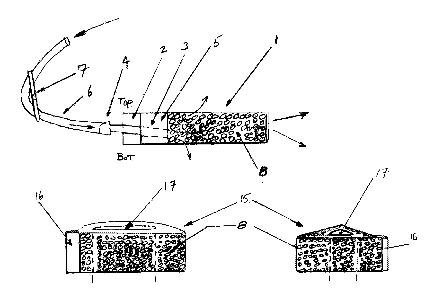
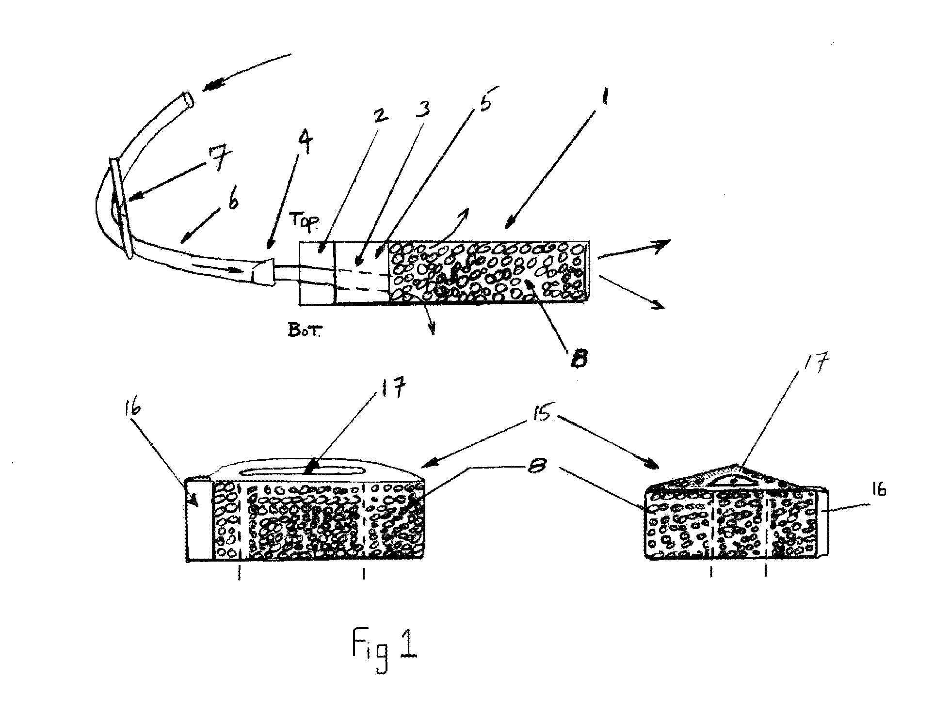
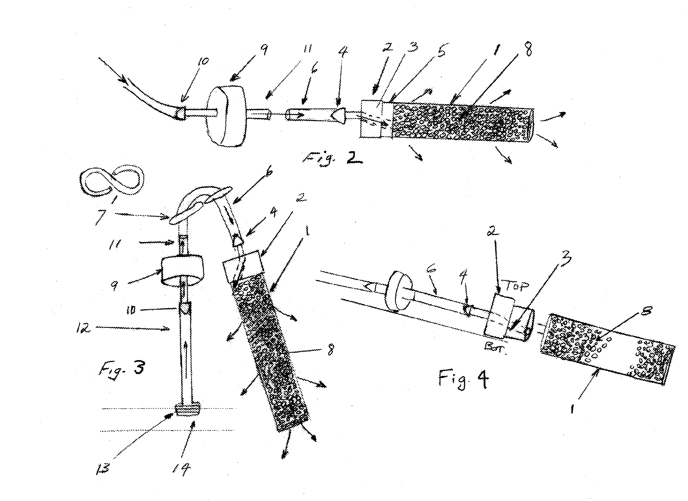
[0018]Each of the three preferred embodiments of the drip irrigation fertilizing system are shown in FIGS. 1 thru 6 and are comprised of the following components:[0019]1. Fertilizer Pouch[0020]2. Nipple[0021]3. Nipple Canal[0022]4. Nipple Barb Tip[0023]5. Nipple Base[0024]6. Drip tubing[0025]7. S Ring Clip[0026]8. Fertilizer Pellets[0027]9. Drip Emitter[0028]10. Emitter Input Port[0029]11. Emitter Output Port[0030]12. Tubular Emitter Support Rod[0031]13. Threaded Support Base[0032]14. Irrigation Line with Threaded Opening[0033]15. Circular Fertilizer Pouch[0034]16. Flexible Pouch Seal[0035]17. Variable Pouch Diameter[0036]18. Bubbler Head[0037]19. Irrigation Pipe Riser[0038]20. Variable Rate Stake Emitter[0039]21. Emitter Support Stake[0040]22. Staked Emitter input Port

[0041]In preferred embodiment one of the present invention shown in FIG. 2, the center of the design is fertilizer pouch 1 which encloses and seals fertilizing medium comprised of small chemical pellets 8 and is attac...


PUM


Abstract

An irrigation fertilizing system employing a water porous mesh pouch containing a slow dissolving fertilizing medium and attaching directly to a drip type emitter device via a tube fitting or indirectly below a standard irrigation bubbler emitter or drip adjustable flow emitter by means of a flexible fitted pouch design, which allows it to be held in place under the emitter output.

Description

BACKGROUND OF INVENTION[0001]1. Field of Invention[0002]The present invention relates to the field of irrigation devices designed to conserve water, such as low volume drip irrigation emitters, bubblers, micro bubblers and any watering emitter whose output is limited in volume and is concentrated in a small given circumference around itself. More specific, in one embodiment, the present invention relates to a method and system for attaching a fertilizing device to a standard drip irrigation emitter, providing a site and fertilizer specific design that is low cost, replaceable, and which provides fertilizer each time the emitter releases water in the watering cycle of the drip irrigation system. In a second embodiment of this design, the present invention relates to a method and system for attaching a fertilizing device underneath a standard bubbler irrigation device or underneath any number of micro bubblers and micro sprinkler devices, which in the same manner provide fertilizer ea...

Claims


Application Information

Patent Timeline
IPC IPC(8): B05B17/04
CPCA01G25/02Y02P60/21Y02A40/22
Inventor ROIDE, PAUL ANTHONY
Owner ROIDE PAUL ANTHONY
Why Eureka
Try Eureka