Inflation switch device with temperature rise current exceeding 4000 A

A switchgear and current technology, applied in the setting of switchgear, cooling/ventilation of substation/switchgear, electrical components, etc., can solve the problem of affecting the stability and service life of switchgear, reducing the insulation of insulating parts, and increasing the degree of overheating and other issues, to achieve the effect of improving heat dissipation, prolonging service life, and saving money

Pending Publication Date: 2022-08-09
GUANGZHOU BAIYUN ELECTRIC EQUIP
View PDF0 Cites 0 Cited by
  • Summary
  • Abstract
  • Description
  • Claims
  • Application Information

AI Technical Summary

Problems solved by technology

Practice has proved that the problem of temperature rise seriously affects the stability and service life of the switchgear. Moreover, the problem of overheating is a continuous development process. If it is not controlled, the degree of overheating will continue to increase, and it will affect the performance of insulating parts and equipment life. Firstly, it will reduce the insulation of the insulating parts. Secondly, due to the large temperature change, the components in the cabinet will have different degrees of expansion. Unsynchronized expansion will cause cracking and deformation of components, or cause air chambers Leakage, etc., resulting in more serious consequences

Method used


Image

  • Inflation switch device with temperature rise current exceeding 4000 A
  • Inflation switch device with temperature rise current exceeding 4000 A
  • Inflation switch device with temperature rise current exceeding 4000 A

Examples


Embodiment Construction

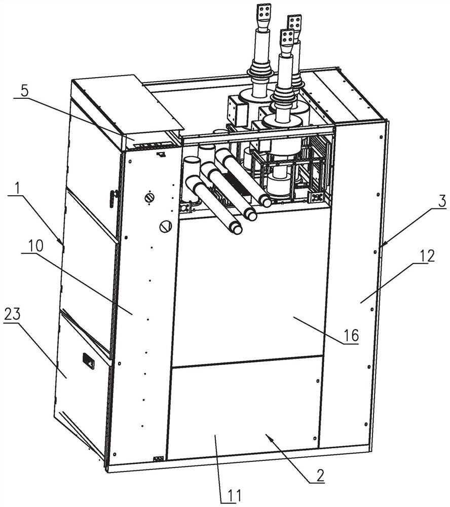
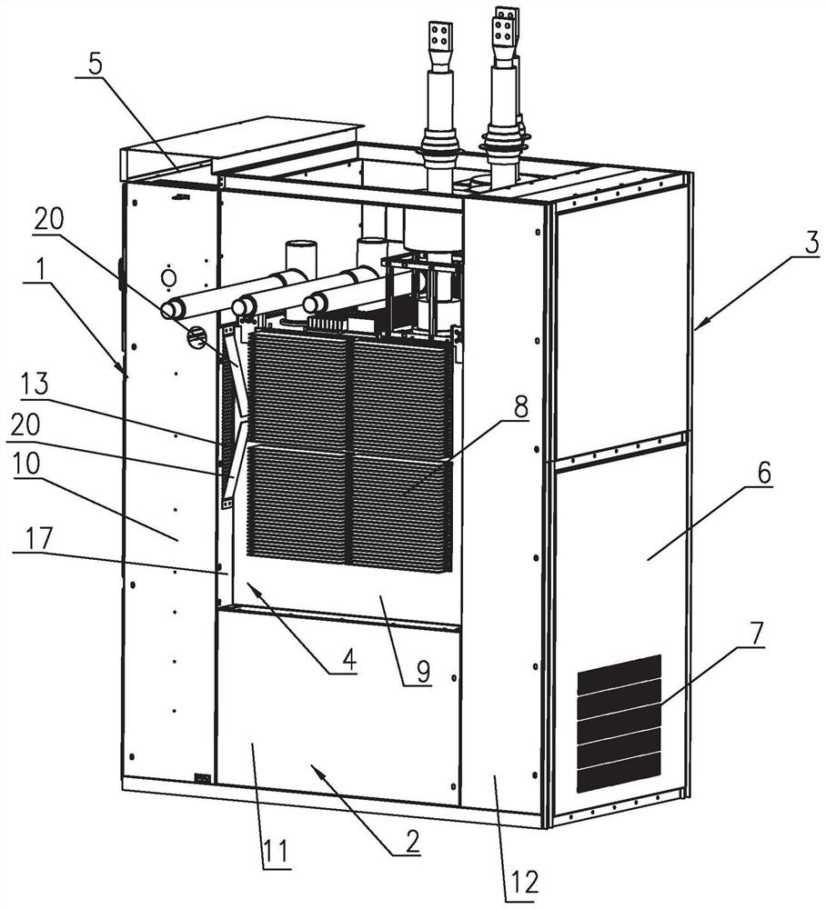
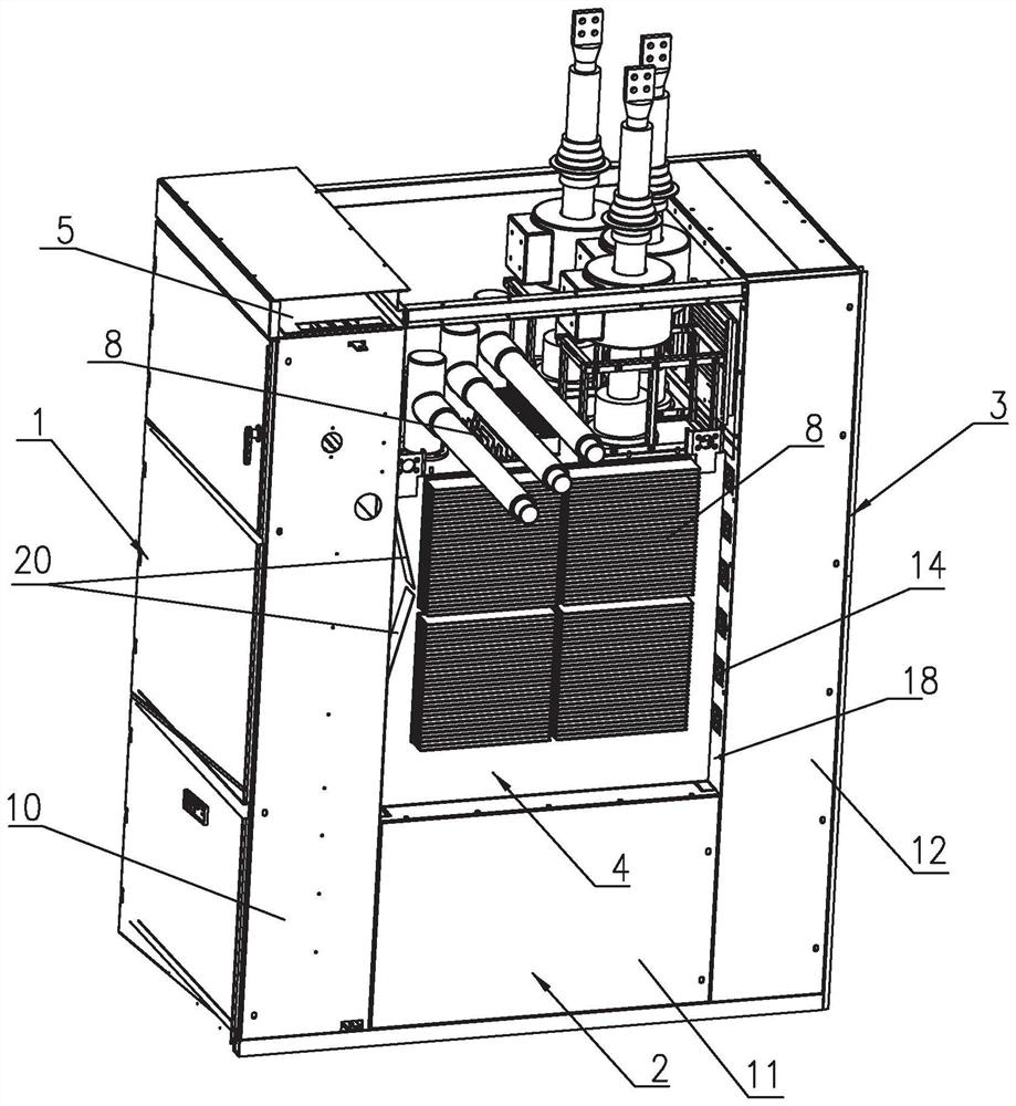
[0031] like Figures 1 to 7As shown, it is an inflatable switchgear of the present invention with a temperature rise current exceeding 4000A, including a front cabinet 1, a middle cabinet 2, a rear cabinet 3 and an air box 4, and the air box 4 is arranged on the top surface of the middle cabinet 2 and is located in the front cabinet. 1 and the rear cabinet 3, the top of the front cabinet 1 is provided with a first air inlet 5, the rear panel 6 of the rear cabinet 3 is provided with a second air inlet 7, and the second air inlet 7 is located at the bottom of the rear panel 6. , the two side panels 10 of the front cabinet 1, the two side panels 11 of the middle cabinet 2, the two side panels 12 of the rear cabinet 3 and the two side panels 9 of the air box 4 respectively have a height difference to form a recess. The two side plates 9 and the top plate are provided with heat dissipation plates 8. In this embodiment, studs are welded on the two side plates 9, and four aluminum al...


PUM


Abstract

The invention discloses an air inflation switch device with temperature rise current exceeding 4000 A. The air inflation switch device comprises a front cabinet, a middle cabinet, a rear cabinet and an air box, a first air inlet is formed in the top of the front cabinet, a second air inlet is formed in a rear end plate of the rear cabinet, and height differences exist between two side plates of the front cabinet, the middle cabinet and the rear cabinet and two side plates of the air box to form concave parts. Heat dissipation plates are arranged on two side plates and a top plate of the air box, a first opening is formed in the front side face of the concave portion, a first fan is installed on the rear side face of the concave portion, and an air outlet is formed in the position, higher than the top plate of the air box, of the front end plate of the rear cabinet and provided with a second fan. A cover plate for sealing the concave part is mounted at the edge of the concave part, so that a heat dissipation channel is formed in a space between the gas tank side plate and the cover plate; and a space above the gas tank top plate and between the front cabinet and the rear cabinet is an open space. According to the invention, the heat dissipation effect is improved, the safe and stable operation is still realized when the temperature rise current exceeds 4000 A, the service life is prolonged, the maintenance is convenient, and the device can be formed by transforming the existing gas-filled switch equipment, and is economical.

Description

technical field [0001] The invention relates to a gas-filled switch device, in particular to a gas-filled switch device with a temperature rise current exceeding 4000A. Background technique [0002] The series gas-insulated metal-enclosed switchgear (C-GIS) belongs to the power distribution equipment in the medium voltage field. It is welded, and the primary flow part is encapsulated in a closed air chamber. The relative air pressure inside the air chamber is 0.02 to 0.05 MPa. The gas is generally pure SF6 gas, compressed air, compressed N2, compressed CO2, CF4, C-C4F8, C3F8, C2F6, CF3I, and mixtures of SF6 and the above gases. [0003] The series of gas-insulated metal-enclosed switchgears are suitable for receiving and distributing electric energy in 7.2~40.5kV power transmission and distribution systems, realizing real-time control, protection, measurement, monitoring, communication and other functions of the power system under normal operation and fault conditions. It ...

Claims


Application Information

Patent Timeline
Patent Type & Authority Applications(China)
IPC IPC(8): H02B13/045H02B13/025H02B1/56H02B1/28H02B1/30
CPCH02B13/045H02B13/025H02B1/565H02B1/28H02B1/30
Inventor 侯立伟丁冠仁李元鹏刘小平凌永浩关庆坤徐俊杰
Owner GUANGZHOU BAIYUN ELECTRIC EQUIP
Why Eureka
Try Eureka