
Cable actuated drain

a technology of actuating drains and cables, applied in water installations, construction, domestic plumbing, etc., can solve the problems of complicated maintenance or repair of current devices, complicated drawbacks of current devices, and problems such as corrosion resistance, and achieve the effect of facilitating rotation and corrosion resistan

Active Publication Date: 2011-01-06
WCM IND INC
View PDF42 Cites 27 Cited by
  • Summary
  • Abstract
  • Description
  • Claims
  • Application Information

AI Technical Summary

Benefits of technology

[0010]It is another aspect of the present invention to provide a drain system that does not require an access panel to reach the cable and associated components. It will be appreciated that such a system will reduce costs and complexity associated with a bathtub installation. That is, the need to accommodate the access panel or to repair stone, tile, or other similar materials associated with a bathtub are alleviated. The cable and associated components of one embodiment of the present invention may be repaired from inside the bathtub by way of the overflow port. More specifically, to facilitate repairs the cover of the overflow system and / or drain is removed to reveal the inner workings of the drain actuating system, which can then be easily replaced.
[0011]It is another aspect of the present invention to provide a system that can be pressure tested. As disclosed in various patents and issued publications listed above related to overflow assemblies, embodiments of the present invention include a mechanism to selectively obstruct flow of water through the overflow system. That is, it is often required or desirable to test a plumbing system by blocking overflow ports, drains and inlets to the basin by filling the plumbing system of a house with water or air to assess leakage of any of the components. In order to facilitate these tests, the overflow port, for example, is often plugged with a balloon or a cap. One embodiment of the present invention, however, includes a diaphragm that is associated with the overflow port. After all testing is completed, the thin diaphragm is removed and discarded. This type of diaphragm helps address complexities of pressure testing a plumbing system and thus reduces costs. One of skill in the art will also appreciate that a plug, cap, or other flow preventing device may be employed instead of the diaphragm without departing from the scope of the invention.
[0013]It is another aspect of the present invention to employ a cable that is made of plastic instead of a braided or solid metal cables. Preferably, such cables are lighter, more flexible and corrosion resistant than metal cables.
[0014]It is yet another aspect of the present invention to provide an overflow cap having a handle or knob associated therewith that facilitates rotation thereof. Such a device would be ideal to be used by individuals of limited dexterity, such as the elderly or handicapped.
[0021]In a related aspect of the present invention, embodiments of the present invention employ a common strainer body, which reduces inventory and facilitates repair or retrofit when the stopper assembly requires replacement.
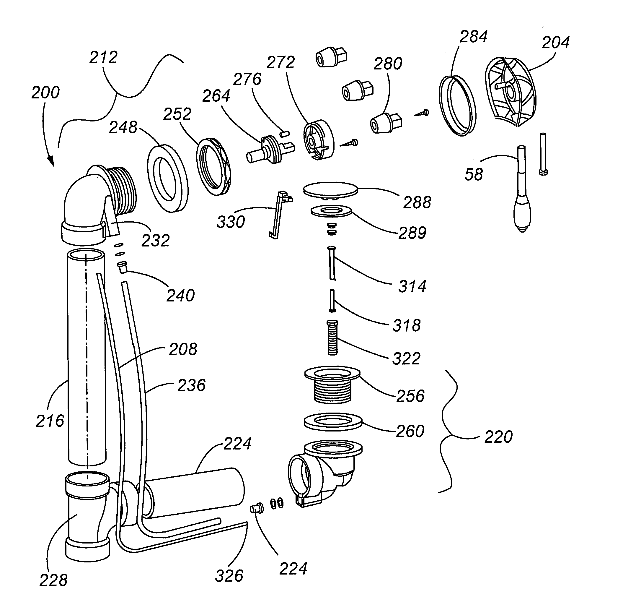
[0024]It is thus one aspect of the present invention to provide a system for controlling a drain stopper that includes an overflow assembly; a drain assembly, which includes said drain stopper, that is selectively moved relative to a strainer body to control the flow of fluid through the drain assembly; a cable drive shaft having a cam rotatably associated with said overflow assembly; a cable having a first end associated with said cam of said cable drive shaft and a second end associated with said drain assembly; a sheath associated with said overflow assembly and said drain assembly wherein said cable is positioned within an internal volume of said sheath and is able to slide freely therein; and wherein rotation of said cable driveshaft moves said cable within said sheath to thus move said second end of said cable from a first position of use to a second position of use to move said drain stopper relative to said strainer body.

Problems solved by technology

Drain manipulation and control devices that employ chains and cables suffer from problems posed by corrosion, chain tangling, and rigidity issues.
These drawbacks of current devices are further compounded by the fact that they are generally inaccessible for repair.
As these devices are typically located within the tub or surrounding structure, maintenance or repair thereof is complicated and costly.
Typically, unless the original installer provided an access panel, costly removal, replacement, and repair of the stone, tile, or other material surrounding the drain is necessary.
One drawback of Kreuzer is that the cable is located on the inside of the drain pipe.
The problem with this configuration is that the cable cannot be easily adjusted to accommodate overflow assemblies of various lengths.
Providing a fixed length of cable as taught by Kreuzer does not allow length adjustment and, thus, may require modification by the installer.
Yet another problem with Kreuzer is that turning of the handle is not efficiently transferred into movement that is needed to turn the lever.
This deficiency is related to the fact that nothing is constraining or guiding the movement of the cable.
One drawback of Gebert is that it includes a bellows portion that does not meet building code requirements.
Gebert also mentions that cable twisting caused by a lever associated with the drain is an issue of the prior art.
Namely, the drawbacks of the prior art include the need for complicated drain actuating mechanisms and they suffer from the inability to access all of the internal components of the drain opening system.
As will be appreciated by one skilled in the art, the fabrication of these access panels is costly and complicated and may be unsightly.

Method used


Image

  • Cable actuated drain
  • Cable actuated drain
  • Cable actuated drain

Examples


Embodiment Construction

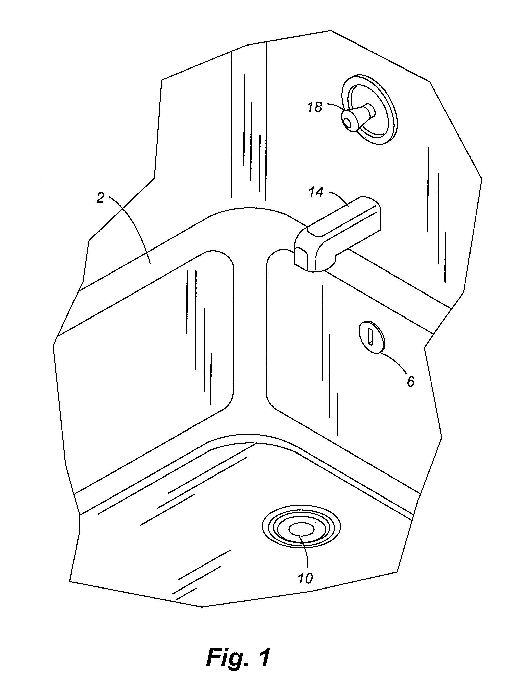
[0133]FIG. 1 shows a bathtub 2 having an overflow port 6 and a drain port 10. The bathtub 2 is filled with water by way of a water inlet 14 where a knob 18 is rotated.

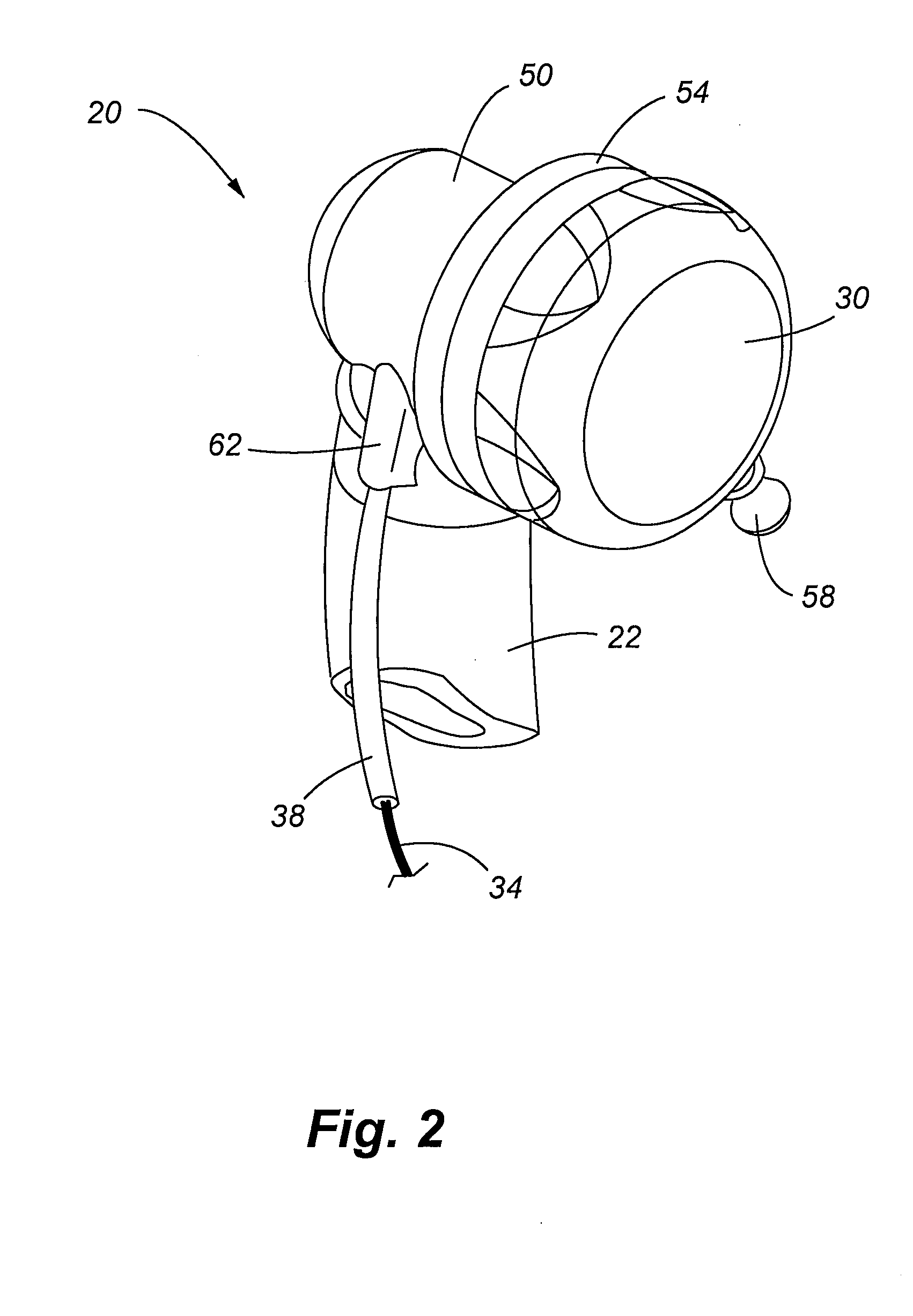
[0134]Referring now to FIGS. 2-7, the cable actuated drain assembly 1 of one embodiment of the present invention is shown that employs an overflow assembly 20 with an overflow pipe 22 and a drain assembly 24 with a drain pipe 26. The overflow pipe 22 includes a rotatable overflow cap 30 that is associated with a cable 34 situated in a sheath 38. The cable 34 is also associated with a post 42 of the drain assembly 24 wherein selective rotation of the cap 30 moves a head 46 of the drain assembly 24 from a first position of use to a second position of use and positions therebetween. In one embodiment rotation of the cap 30 about 70 degrees moves the head 46.

[0135]Referring now specifically to FIG. 2, the overflow assembly 20 is shown that is comprised of an overflow elbow 50 interconnected to the overflow pipe 22. The ove...


PUM


Abstract

An improved drain actuates system that includes a cable to actuate a head or stopper of a drain. More specifically, one end of the cable is associated with the drain without additional moving parts and another end of the cable associated with an overflow cap of an overflow system wherein rotation of the overflow cap selectively moves the cable to move the head of the drain. The internal components associated with the overflow end of the cable that allow it to actuate the drain are fully accessible through the overflow port of the plumbing system.

Description

[0001]This application is a Continuation-In-Part of U.S. patent application Ser. No. 12 / 542,205, filed Aug. 17, 2009, which claims the benefit of U.S. Provisional Patent Application Ser. No. 61 / 089,692 filed Aug. 18, 2008, the entire disclosures which are incorporated by reference herein.FIELD OF THE INVENTION[0002]Embodiments of the present invention are generally related to devices for facilitating the opening and closing of a stopper or other closure device associated with a drain of a bathtub or other fluid-holding basin. One embodiment of the present invention, specifically, employs a sheathed cable that is associated with a portion of the overflow assembly of a bathtub that actuates a stopper by adjusting a cap of the overflow assembly.BACKGROUND OF THE INVENTION[0003]A number of cable and chain devices currently exist that allow for manipulation of drain position in a bathtub, a washbasin, a hot tub, a baptismal, a Jacuzzi-type product, and other similar devices (hereinafter ...

Claims


Application Information

Patent Timeline
Patent Type & Authority Applications(United States)
IPC IPC(8): E03C1/12
CPCE03C1/2304E03C2001/2315E03C1/232
Inventor BALL, WILLIAM T.PILARCZYK, ERICHOGAN, KEVINRIESCO, CARLCARLSON, WILLIAM L.
Owner WCM IND INC
Learn More