
Dynamic tag allocation in a multithreaded out-of-order processor

a multi-threaded out-of-order, dynamic tag technology, applied in the field of dynamic tag allocation, can solve problems such as incorrect processor sta

Active Publication Date: 2010-12-30
ORACLE INT CORP
View PDF7 Cites 37 Cited by
  • Summary
  • Abstract
  • Description
  • Claims
  • Application Information

AI Technical Summary

Benefits of technology

[0009]In yet another embodiment, a method is disclosed in which a reorder buffer in a multithreaded computer processor receives a first indication that a first tag value has been assigned to a first plurality of instructions being executed. The instructions may be executed within a first thread of the processor. The reorder buffer receives a second indication that a second tag value has been assigned to a second plurality of instructions within the first thread, where the second plurality of instructions is immediately subsequent to the first plurality of instructions according to a program order for the first thread. The reorder buffer also stores first and second entries in a memory, respectively corresponding to the first and second pluralities of instructions. Information is stored in the first entry indicating that the second plurality of instructions is immediately subsequent to the first plurality of instructions in program order. The reorder buffer receives information indicating the first plurality of instructions are ready to commit. (This may occur, for example, when the reorder buffer receives an indication that one or more instructions have completed execution.) The reorder buffer accesses the first entry in the memory to retrieve the indication of the second entry of the memory. Information indicating the second plurality of instructions are ready to be committed is received at the reorder buffer. The reorder buffer causes the first plurality of instructions to be committed (this may occur, for example, by sending information to a commit pipeline or commit unit). Subsequently, the reorder buffer causes the second plurality of instructions to be committed.

Problems solved by technology

Otherwise, an incorrect processor state may result.

Method used


Image

  • Dynamic tag allocation in a multithreaded out-of-order processor
  • Dynamic tag allocation in a multithreaded out-of-order processor
  • Dynamic tag allocation in a multithreaded out-of-order processor

Examples


Embodiment Construction

[0020]This specification includes references to “one embodiment” or “an embodiment.” The appearances of the phrases “in one embodiment” or “in an embodiment” do not necessarily refer to the same embodiment. Particular features, structures, or characteristics may be combined in any suitable manner consistent with this disclosure.

Overview

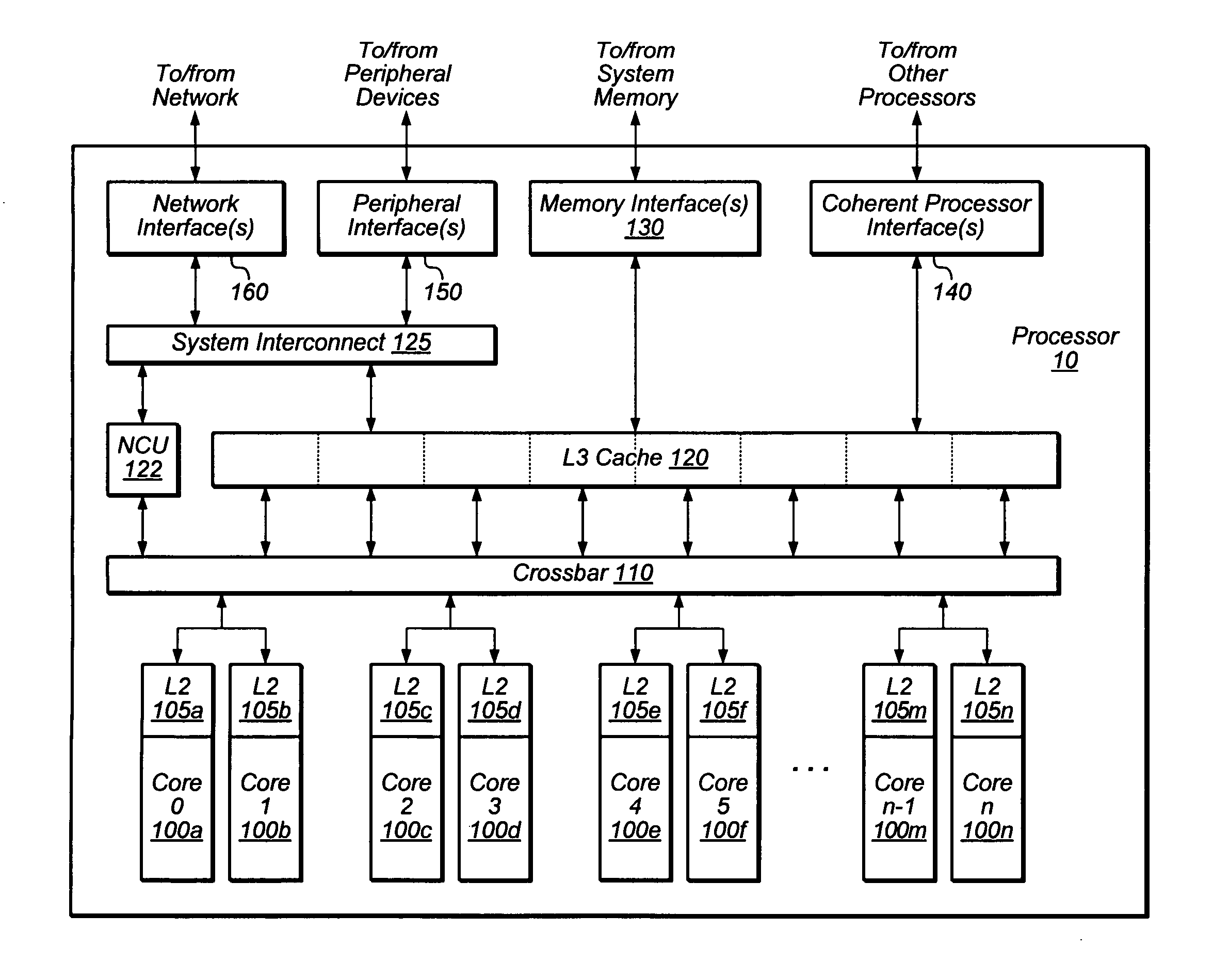
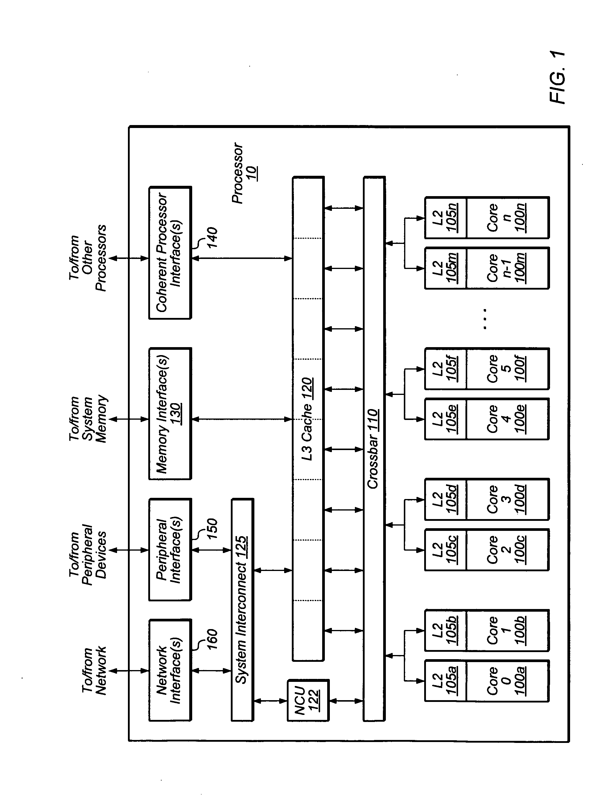
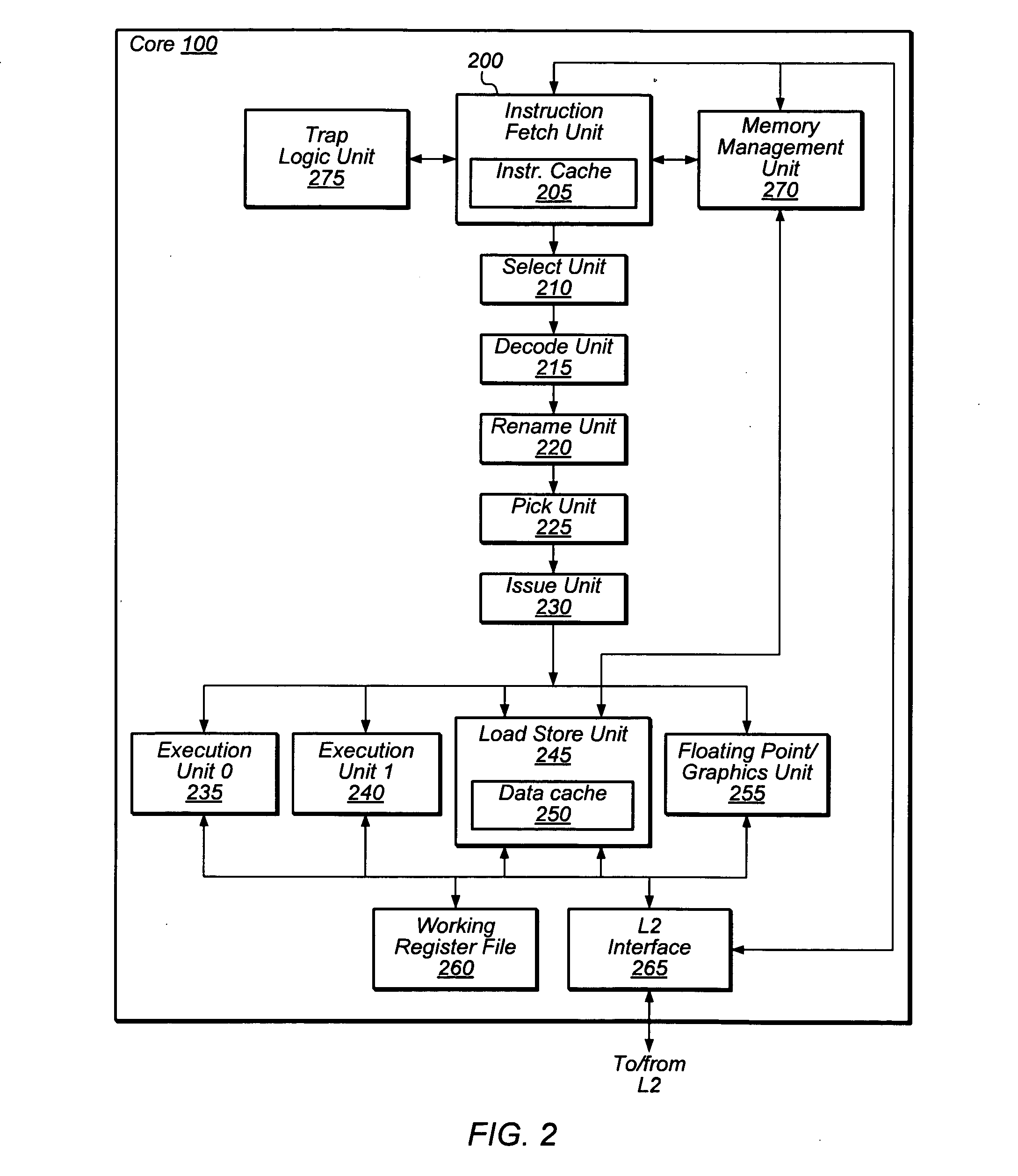
[0021]FIGS. 1-2 present a general overview of an exemplary processor. FIGS. 3-8 discuss the dynamic allocation of tags and the processor's use of instructions having dynamically allocated tags. Lastly, FIG. 9 illustrates an exemplary system in which a processor employing the disclosed techniques may be utilized.

Definitions

[0022]As used herein, the following terms shall be given the following meanings:

[0023]“Program order.” This term has its ordinary and customary meaning in the art, which includes the sequence in which instructions appear in a computer program. A first instruction in a thread may be said to appear “earlier” or “before” or “ahead of” a...


PUM


Abstract

Various techniques for dynamically allocating instruction tags and using those tags are disclosed. These techniques may apply to processors supporting out-of-order execution and to architectures that supports multiple threads. A group of instructions may be assigned a tag value from a pool of available tag values. A tag value may be usable to determine the program order of a group of instructions relative to other instructions in a thread. After the group of instructions has been (or is about to be) committed, the tag value may be freed so that it can be re-used on a second group of instructions. Tag values are dynamically allocated between threads; accordingly, a particular tag value or range of tag values is not dedicated to a particular thread.

Description

BACKGROUND OF THE INVENTION[0001]1. Field of the Invention[0002]This disclosure relates generally to computer processors, and more particularly to dynamically allocating tag values between instructions in different threads of a computer processor.[0003]2. Description of the Related Art[0004]Some computer processors support out-of-order execution, meaning that execution results for instructions in a computer program are not necessarily computed in the order in which the instructions appear in the program (which is referred to as “program order.”) Out-of-order processors typically commit (retire) instructions in program order, regardless of the order in which these instructions are actually executed. Otherwise, an incorrect processor state may result.[0005]To maintain program order, instructions can be assigned sequence numbers. A first instruction may receive a first sequence number, and a second, subsequent instruction may receive a second sequence number indicating that the second ...

Claims


Application Information

Patent Timeline
Patent Type & Authority Applications(United States)
IPC IPC(8): G06F9/46G06F12/08
CPCG06F9/384G06F9/3851G06F9/3885G06F9/3855G06F9/3853G06F9/3856
Inventor JORDAN, PAUL J.GOLLA, ROBERT T.BARREH, JAMA I.
Owner ORACLE INT CORP
Learn More