
Laser Weld Process For Seam Welded Electrochemical Devices

a technology of electrochemical devices and laser welds, which is applied in the direction of cell components, manufacturing tools, cell component details, etc., can solve the problems of internal components that can damage the casing inside the casing

Active Publication Date: 2010-12-30
WILSON GREATBATCH LTD
View PDF11 Cites 20 Cited by
  • Summary
  • Abstract
  • Description
  • Claims
  • Application Information

AI Technical Summary

Benefits of technology

[0008]It is, therefore, an object of this invention to provide a method for welding a seam of an electrochemical device in a manner that reduces the internal peak temperature below the point where damage can occur, yet still achieves the necessary weld penetration and microstructure throughout the entire welded seam.
[0014]Additionally, the laser may be moved linearly so that the length of the laser beam is maintained constant. In other words, the distance from the laser output optics to the point of incidence on the interface between the casing members is maintained constant. In this manner, the focus of the laser on the interface is maintained, and a more uniform seam weld is obtained.
[0015]The laser may also be moved linearly and rotationally during its traverse completely around and along the perimeters of the first and second casing members, such that the laser beam is maintained perpendicular to the first surrounding sidewall of the first casing member and the second surrounding sidewall of the second casing member. By maintaining the angle of incidence of the laser perpendicular to the casing members, the spot size of the laser on the interface is maintained. This results in a more uniform seam weld. Additionally, data on the particular size and shape of the device being welded may be provided to a control system. The various linear and rotational actuators that direct the laser beam and / or rotate the casing members may be controlled in a manner so that the rate of advancement of the laser beam along the interface between the first and second casing members is maintained constant. Such control also provides a more uniform seam weld.

Problems solved by technology

The seam welding operation requires significant heat input at the interface of the casing halves, which produce temperatures within the casing that can damage the internal components.

Method used


Image

  • Laser Weld Process For Seam Welded Electrochemical Devices
  • Laser Weld Process For Seam Welded Electrochemical Devices
  • Laser Weld Process For Seam Welded Electrochemical Devices

Examples


Embodiment Construction

[0031]For a general understanding of the present invention, reference is made to the drawings. In the drawings, like reference numerals have been used throughout to designate identical elements.

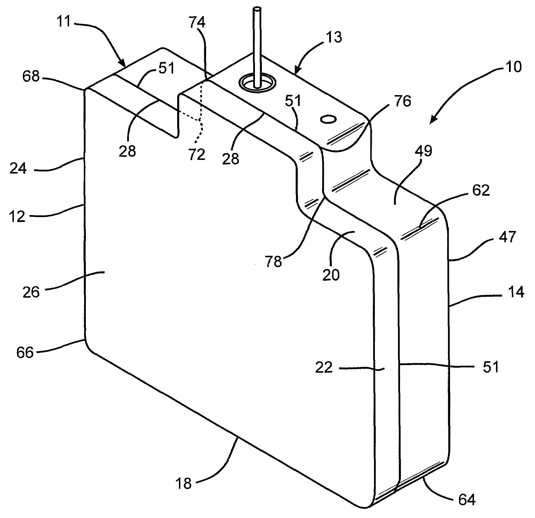
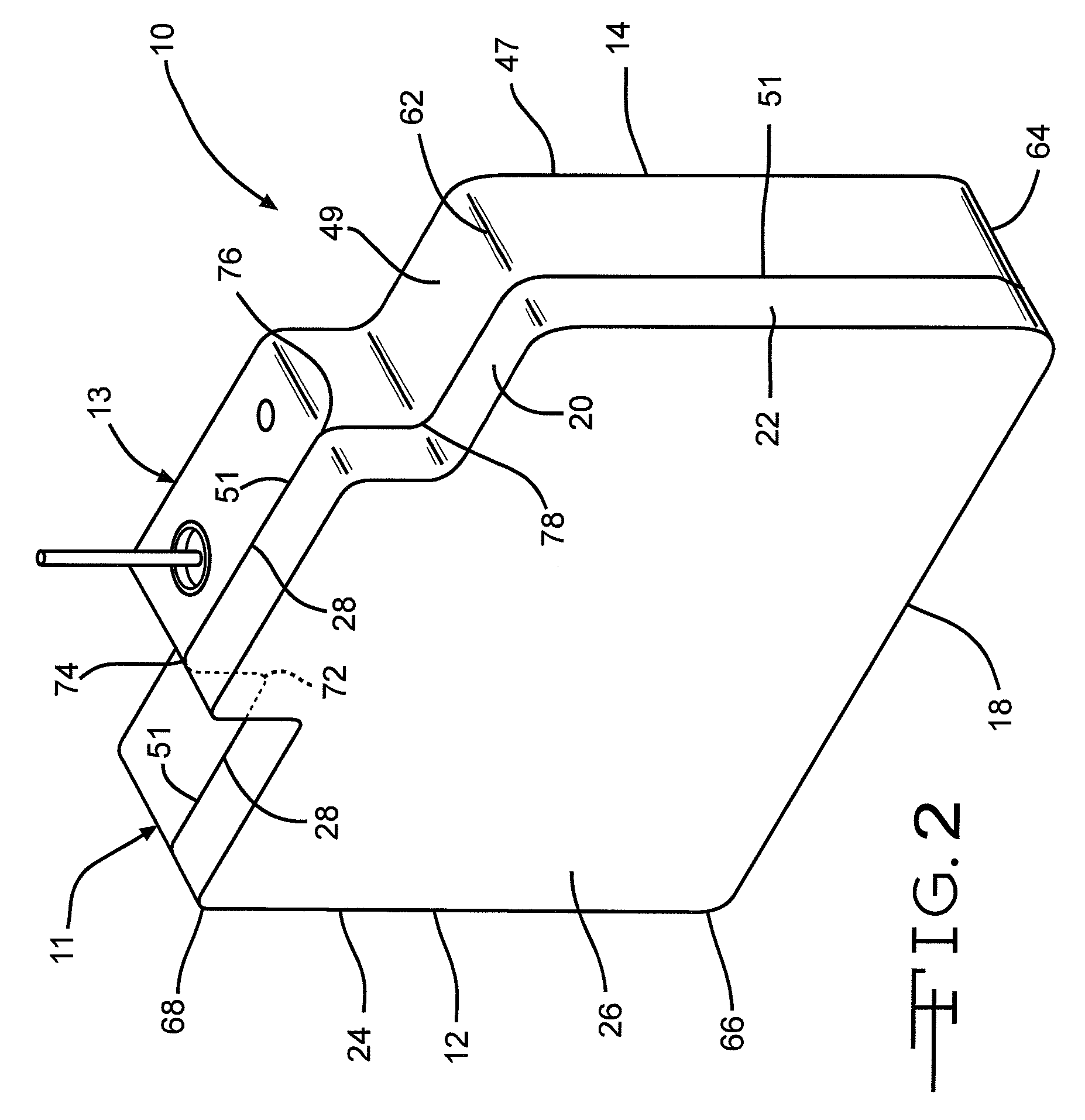
[0032]In the method of the present invention, short sections of a hermetic seam are sequentially welded in a manner that reduces the internal peak temperature within the electrochemical device enclosure below that at which damage to the internal components can occur. However, the welding process still achieves the necessary weld penetration and microstructure throughout the entire hermetic weld seam.

[0033]The series of separated welded segments are of limited length and have sufficient unwelded distance there between to limit the amount of heat generated at a given weld location. The unwelded portions between weld segments are subsequently welded after a sufficient amount of time has passed to allow for heat dissipation, thereby limiting the internal peak temperature produced anywhere along t...


PUM

PropertyMeasurementUnit
Timeaaaaaaaaaa
Angleaaaaaaaaaa
Lengthaaaaaaaaaa

Abstract

A method for making an electrochemical device enclosure is described. The methods comprises the steps of forming first and second casing members; inserting electrochemically active materials within the first casing member; mating the first casing member to the second casing member, thereby forming an interface therebetween; providing a laser welding apparatus comprising a laser; intermittently turning a laser beam on and off while traversing the laser in a first welding pass 360 degrees along the perimeters of the first and second casing members, thereby forming a first intermittent set of welded and unwelded sections at the interface between the casing members; and intermittently turning the laser beam on and off while traversing the laser in a second welding pass 360 degrees along the perimeters of the first and second casing members, thereby forming a second intermittent set of welded sections at the interface between the first and second casing members. The first and second intermitted welded sections combine to provide a complete hermetic seal around and along the circumference of the casing members interface.

Description

BACKGROUND OF THE INVENTION[0001]1. Field of the Invention[0002]The present invention relates generally to the fabrication of enclosures for electrochemical devices. More particularly, the present invention relates in one embodiment to sealing two portions of an electrochemical device enclosure to each other by a laser welding process.[0003]2. Description of Related Art[0004]Improving packaging efficiency of electrochemical devices such as electrochemical cells and capacitors is critical to many applications, especially for implanted devices. Hence, any space within the electrochemical device that can be utilized for active material contributes to improving the overall performance and longevity of the electrochemical device and, therefore, that of the implantable device that is being powered. For devices that are contained within enclosures comprised of two portions that are welded together, clearances must be provided in proximity to laser welds (or other fusion joining structures)...

Claims


Application Information

Patent Timeline
IPC IPC(8): B23K26/00
CPCB23K26/28B23K26/203B23K26/211
Inventor FREITAG, GARY L.FRUSTACI, DOMINICKROY, MARK J.
Owner WILSON GREATBATCH LTD
Learn More