Spherical orienting device and method for manufacturing the same

Inactive Publication Date: 2010-12-23
ROBERT BOSCH GMBH
View PDF11 Cites 19 Cited by
  • Summary
  • Abstract
  • Description
  • Claims
  • Application Information

AI Technical Summary

Benefits of technology

[0011]Because the first support joint is disposed for rotation about the orientation axis of the orientable device, the rotational movement of the middle member with respect to the orientable device describes a generated surface of rotational symmetry around the orientation axis. This enables the middle member to be formed according to an outer contour of the orientable device even when the orientable device substantially deviates from a spherical shape. In particular in typical cases such as mirrors, lenses, cameras, joysticks, cannons or nozzles, where orientable devices typically are flat, disk-like or elongate, tube-like objects that deviate clearly from spherical symmetry but exhibit at least in portions an approximate rotational symmetry around the orientation axis, the middle member is enabled to be shaped to closely conform to the outer contour of the orientable device with minimal gap. Therefore, little installation space is required, while reliable high-speed operation is enabled through a minimized moment of inertia and prevention of parasitic movements.
[0019]According to an example embodiment, the method further comprises forming at least one of the first support joint, the second support joint and the middle revolute joint as an elastic joint from the substrate. This enables further miniaturization and cost reduction since less precision is required in manufacturing such elastic joints. Furthermore, the elastic joint can be configured to function as a spring e.g. for returning the orienting device into a neutral position, or as an electric connection to the orientable device.

Problems solved by technology

This leads to an increase of inertia for the outer gimbal, hindering fast movements, which are required in many applications.
Due to such presence of material at the center of rotation, the object cannot be freely positioned within the mechanism, which is unsuitable for many applications.
For example, in a case of the orientable device being a mirror such as in a mirror scanner application, the mechanism does not allow the mirror to be positioned such that the center of rotation lies in the mirror plane.
Since in general applications orientable payload devices such as listed above are typically not spherically shaped, this leads to an undesirable large space requirement, in particular for orientable payload devices considerably deviating from a spherical shape, e.g. flat or elongate pay-loads.
Large distances of the inner, outer, and middle sphere arms from the orientable device furthermore unfavorably influence high-speed operation due to an increased moment of inertia and the possibility of parasitic movements.

Method used


Image

  • Spherical orienting device and method for manufacturing the same
  • Spherical orienting device and method for manufacturing the same
  • Spherical orienting device and method for manufacturing the same

Examples


Embodiment Construction

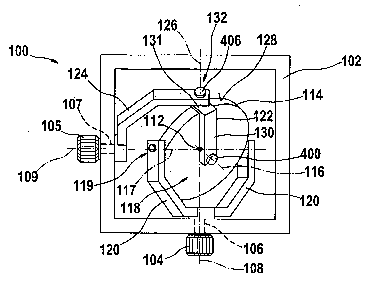
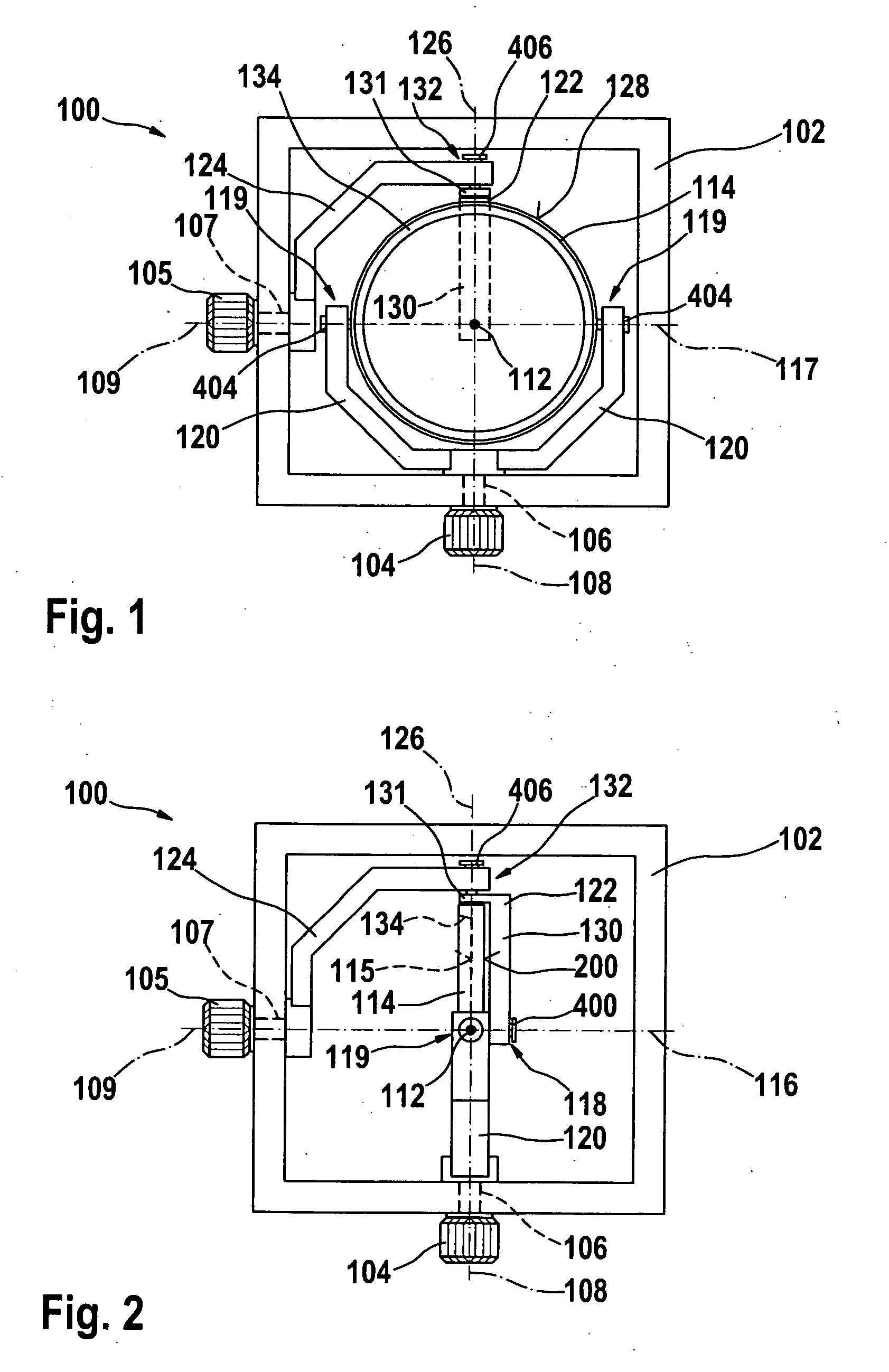
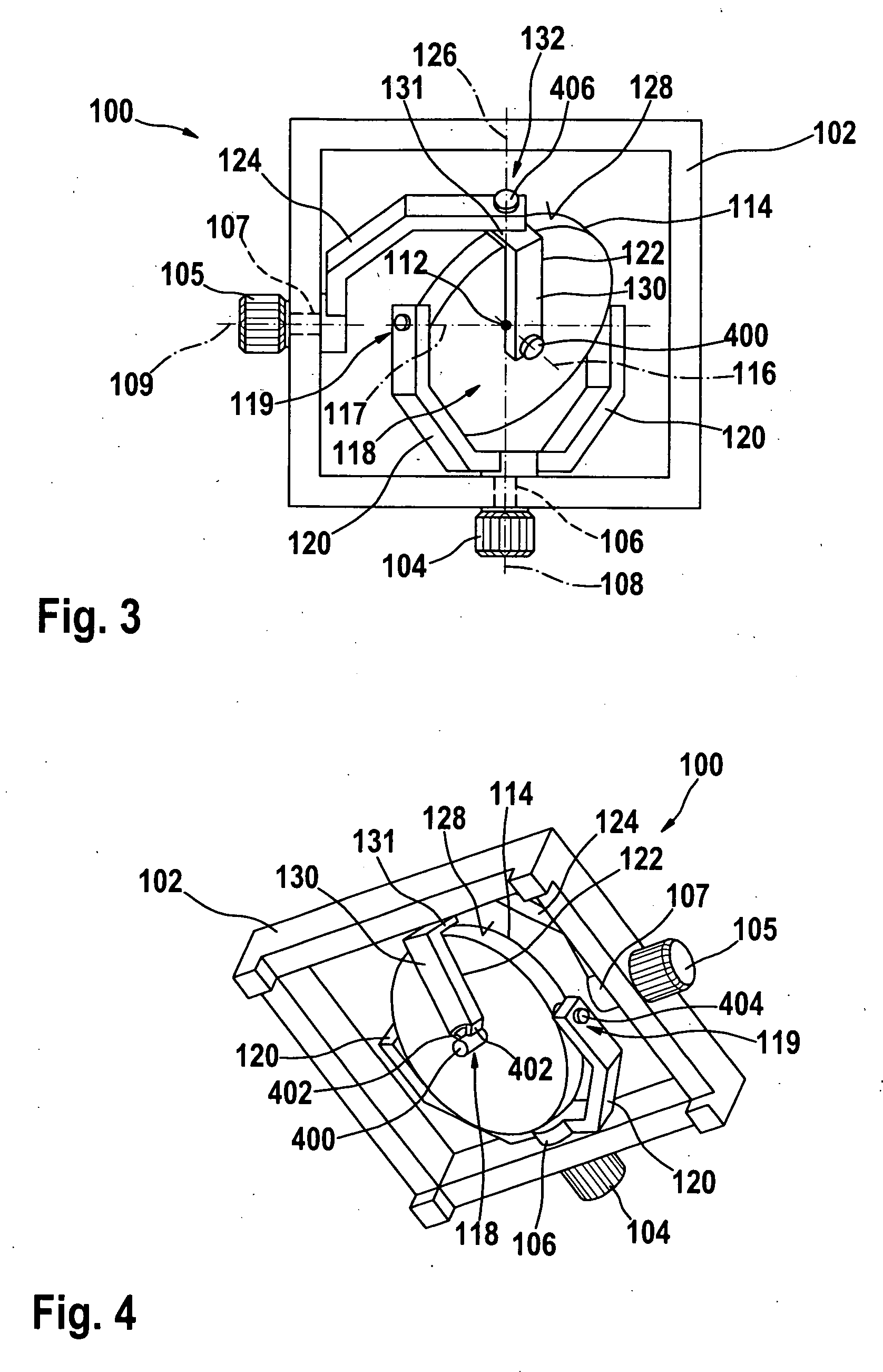
[0026]FIGS. 1-3 depict a spherical orienting device 100 including a mirror 114 as a payload to be oriented in space, relative to a fixed base 102. The base 102 is formed as a rectangular frame, which surrounds the mirror 114. In FIGS. 1-3, the rectangular frame of the base 102 lies in the drawing plane.

[0027]The mirror 114 comprises an outer shape substantially conforming to a disk of rotational symmetry around an orientation axis 116, bounded by a cylindrical peripheral surface 128. FIG. 1 shows the mirror 114 arranged in a neutral position in which it is oriented parallel to the drawing plane, i.e. the plane defined by the base frame 102. The side of the mirror 114 facing the observer comprises a circular reflecting mirror plane 115. A rim 134 circumscribing the mirror plane 115 is formed on the side of the mirror plane 115 along the periphery of the mirror 114, such that the mirror plane 115 as a whole is recessed with respect to the mirror's 114 cylindrical outer shape. In FIGS....


PUM

PropertyMeasurementUnit
Shapeaaaaaaaaaa

Abstract

A spherical orienting device includes a base, first and second actuation shafts, an orientable device, an inner member, a middle member, and an outer member. The first and second actuation shafts are rotatably held by the base for rotary actuation about first and second actuation axes, respectively, which intersect orthogonally at a spherical center of rotation. The orientable device is supported by first and second revolute support joints which are disposed for rotation about an orientation axis of the orientable device and a support axis, respectively. The inner member is fixed to the first actuation shaft and linked to the second support joint. The middle member is inwardly linked to the first support joint and outwardly linked to a middle revolute joint disposed for rotation about a linkage axis. The outer member is fixed to the second actuation shaft and linked to the middle revolute joint.

Description

BACKGROUND OF THE INVENTION[0001]1. Field of the Invention[0002]The present invention relates to a spherical orienting device, e.g., a two degree-of-freedom spherical orientation device driven via two actuation shafts, which supports an orientable device having an orientation axis, and the present invention further relates to a method for manufacturing such a spherical orienting device.[0003]2. Description of Related Art[0004]Two-dimensional spherical orienting devices, which orient an orientable payload device towards a desired direction in space by rotating it around a fixed point, are used in many fields of technology, for example in inertial sensors such as gyrometers, including in micromechanics, in gyroscopes, in orientable mirrors e.g. in two degree-of-freedom optical scanners, in gyroscopic stabilization of cameras and camera objectives, in water cannons for fire trucks or gaming, in robot wrists, artificial hands and in artillery equipment. Another important field of applic...

Claims


Application Information

Patent Timeline
IPC IPC(8): G02B7/00F16M13/02A47G1/24G05G11/00G02B7/198B23P11/00
CPCF16M11/12F16M11/123G02B7/1824Y10S248/913Y10T74/1204Y10T74/12Y10T74/2036Y10T29/49826Y10T74/1289Y10T74/1286F16M11/18
Inventor MAILLARD, PATRICK
Owner ROBERT BOSCH GMBH
Why Eureka
Try Eureka