
Control device for internal combustion engine

a control device and internal combustion engine technology, applied in the direction of electric control, ignition automatic control, machines/engines, etc., can solve the problems of insufficient increase of exhaust gas temperature, inability to perform engine speed control, and difficulty in realizing early warm-up of catalyst devices, so as to prevent excessive correction and maintain early warm-up characteristics of catalyst devices

Inactive Publication Date: 2010-12-23
TOYOTA JIDOSHA KK
View PDF15 Cites 4 Cited by
  • Summary
  • Abstract
  • Description
  • Claims
  • Application Information

AI Technical Summary

Benefits of technology

[0011]Therefore, an object of the present invention is to provide a control device for an internal combustion engine which, at cold starting, can early converge an engine speed to a target speed while restricting rotation variations, and can certainly realize early warm-up of a catalyst device.
[0015]Further, according to a third embodiment in the control device for the internal combustion engine, the control device for the internal combustion engine as described above is characterized in that when a changing quantity of the target speed by the target speed changing means is set in accordance with a difference magnitude between the final ignition timing and the retard lower limit value as a result of the comparing of the comparing means and a magnitude of a feedback integral quantity in the speed feedback control by means of ignition timing for preventing excessive correction.
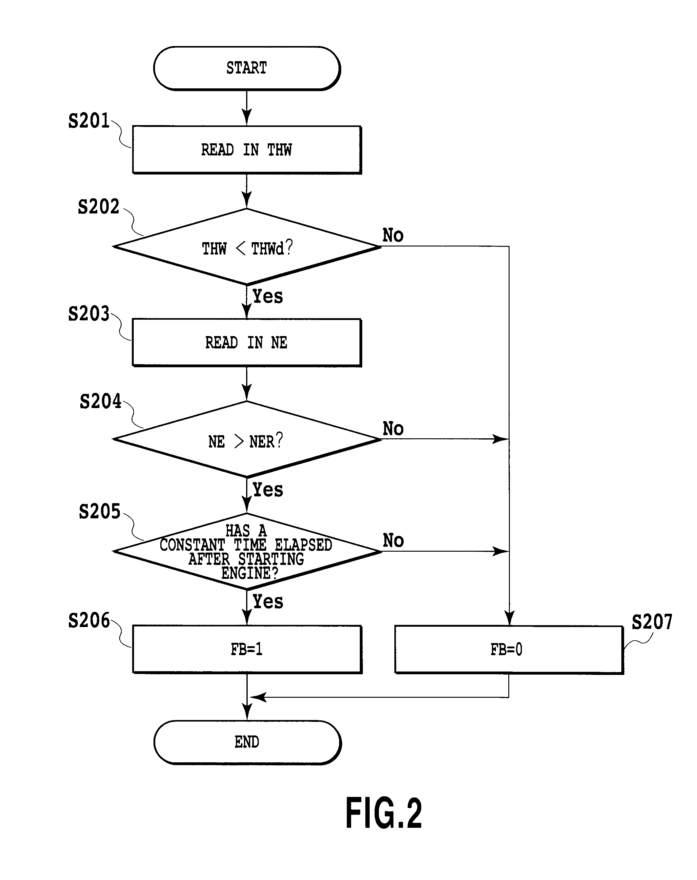
[0018]In addition, according to the first embodiment in the control device for the internal combustion engine in the present invention, when the final ignition timing reaches the retard lower limit value as a result of the comparing by the comparing means, the target speed is increased by the predetermined speed by the target speed changing means, the ignition timing is advanced in response to the increase of the target speed to be back to the range of the speed feedback control by means of ignition timing. Therefore, it is possible to perform the engine speed control by the speed feedback control by means of ignition timing to restrict the rotation variations. In addition, since an intake air quantity for obtaining necessary torque is secured, it is possible to maintain early warm-up characteristics of the catalyst device.
[0019]Further, according to the second embodiment in the control device for the internal combustion engine, when the difference between the final ignition timing and the retard lower limit value exceeds the predetermined angle on an advance side as a result of the comparing by the comparing means, the target speed is decreased by the predetermined speed by the target speed changing means. Therefore, the ignition timing is retarded in response to the reduction of the target speed. Since the exhaust gas temperature can be thus increased, it is possible to realize early warm-up of the catalyst device.

Problems solved by technology

However, when the ignition timing retard control is performed for early warm-up of the catalyst device, the ignition timing results in being close to a retard lower limit value of the ignition timing that is set for reducing torque variations due to combustion deterioration of the engine.
Therefore, the engine speed control can not be performed, thereby raising a problem with occurrence in rotational variations.
Therefore, such rotational variations are restricted, but the ignition timing is to a side more advanced than intended, and therefore, an exhaust gas temperature can not be sufficiently increased.
In consequence, it leads to the problem with the difficulty in realizing early warm-up of the catalyst device.

Method used


Image

  • Control device for internal combustion engine
  • Control device for internal combustion engine
  • Control device for internal combustion engine

Examples


Embodiment Construction

[0028]Hereinafter, embodiments in the present invention will be explained with reference to accompanying drawings.

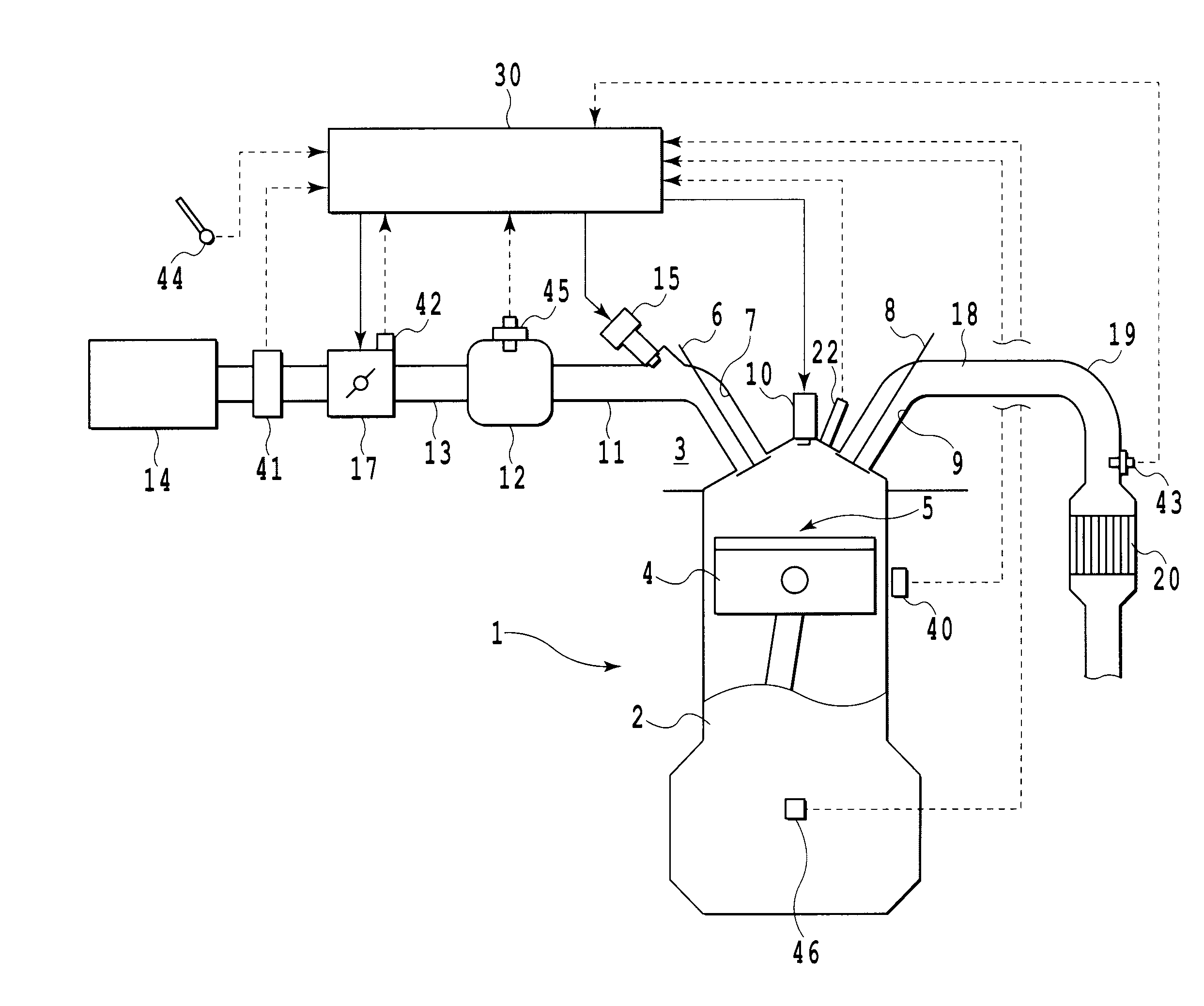
[0029]Here, FIG. 1 is a schematic diagram showing an internal combustion engine in which a control device according to the present invention is mounted. In this figure, numerals 1 to 10 respectively designate an engine body having, for example, four cylinders, a cylinder block, a cylinder head, a piston, a combustion chamber, an intake valve, an intake port, an exhaust valve, an exhaust port, and an ignition plug. The intake port 7 is connected through an intake branch pipe 11 to a surge tank 12 and the surge tank 12 is connected through an intake duct 13 to an air cleaner 14. A fuel injector 15 is arranged in the intake branch pipe 11 and a so-called electronically controlled throttle valve 17 driven by a step motor or the like is arranged in the intake duct 13.

[0030]On the other hand, the exhaust port 9 is connected through an exhaust manifold 18 and an exhaust pipe 19...


PUM


Abstract

A control device for an internal combustion engine which, at cold starting, enables an ignition timing retard control for warm-up of a catalyst device and a speed feedback control by means of ignition timing for converging an engine speed to a target speed includes a function for comparing a final ignition timing with a retard lower limit value, and a function for changing the target speed based upon the result of the comparing. When the final ignition timing reaches the retard lower limit value, the target speed is increased by a predetermined speed and when a difference between the final ignition timing and the retard lower limit value exceeds a predetermined angle on an advance side, the target speed is decreased by a predetermined speed. In this way, at cold starting, the engine speed is early converged to the target speed while restricting rotational variations and early warm-up of a catalyst device can be certainly realized.

Description

TECHNICAL FIELD[0001]The present invention relates to a control device for an internal combustion engine, and more particularly to a control device for an internal combustion engine which appropriately controls an engine speed at cold starting.BACKGROUND ART[0002]In general, it is preferable that a catalyst device provided in an engine exhaust system is early warmed up at cold starting to be capable of purifying an exhaust gas at an early stage after engine starting. Therefore, there is known a technology of retarding an ignition timing from a usual ignition timing to increase an exhaust gas temperature.[0003]There is also known an internal combustion engine in which, for maintaining an engine speed at a predetermined target idle-speed at cold starting, an intake air quantity or ignition timing is feedback-controlled (for example, refer to Patent Documents 1 to 4).[0004]The internal combustion engine described in Patent Document (Japanese Patent Application Laid-Open No. 2006-132543...

Claims


Application Information

Patent Timeline
Patent Type & Authority Applications(United States)
IPC IPC(8): F02P5/04
CPCF02D41/0205Y02T10/46F02P5/1506F02D41/064Y02T10/40
Inventor SATA, KOTAUEDA, KOICHI
Owner TOYOTA JIDOSHA KK
Learn More