
Ophthalmic surgical microscope having an OCT-system

a surgical microscope and oct-system technology, applied in the field of ophthalmic surgical microscopes, to achieve the effect of good resolution

Active Publication Date: 2010-12-09
CARL ZEISS MEDITEC AG
View PDF14 Cites 32 Cited by
  • Summary
  • Abstract
  • Description
  • Claims
  • Application Information

AI Technical Summary

Benefits of technology

This configuration allows for the recording of OCT-section images with minimal intensity loss, enabling efficient scanning of various eye sections with high resolution and flexibility in focal plane adjustment, improving the examination of both the anterior section and ocular fundus without the need to move the surgical microscope.

Problems solved by technology

An interference signal results because of the superposition.

Method used


Image

  • Ophthalmic surgical microscope having an OCT-system
  • Ophthalmic surgical microscope having an OCT-system
  • Ophthalmic surgical microscope having an OCT-system

Examples


Embodiment Construction

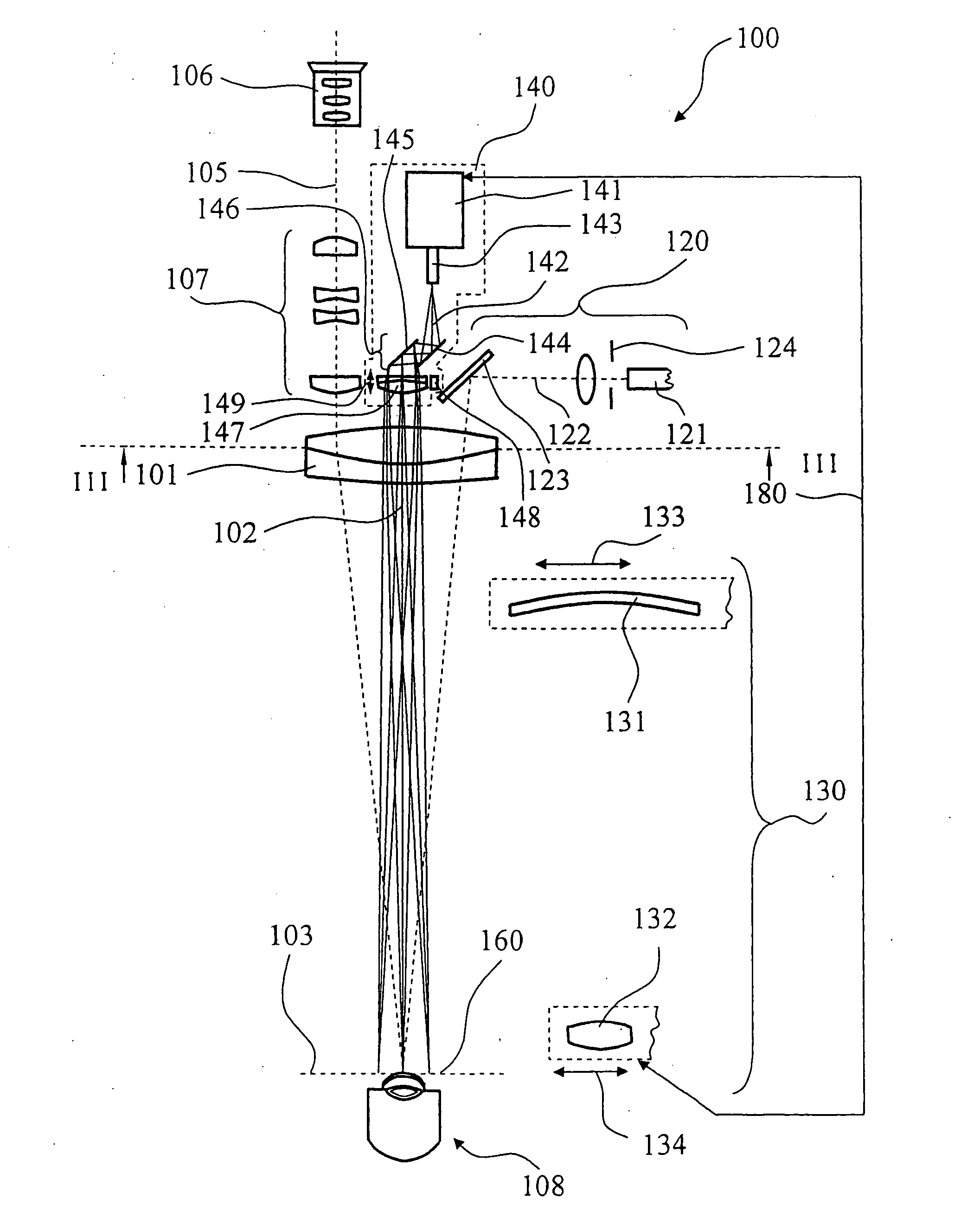
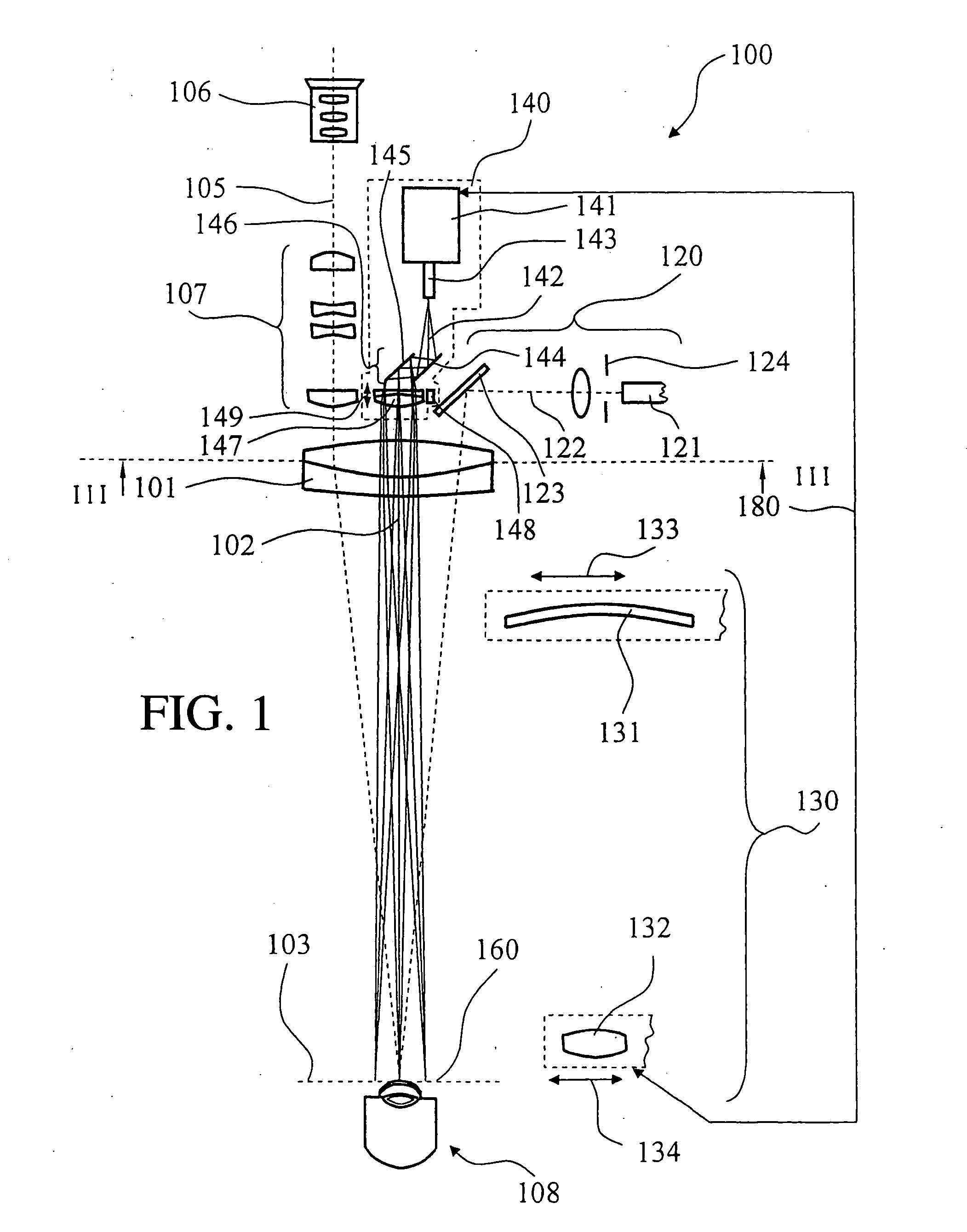
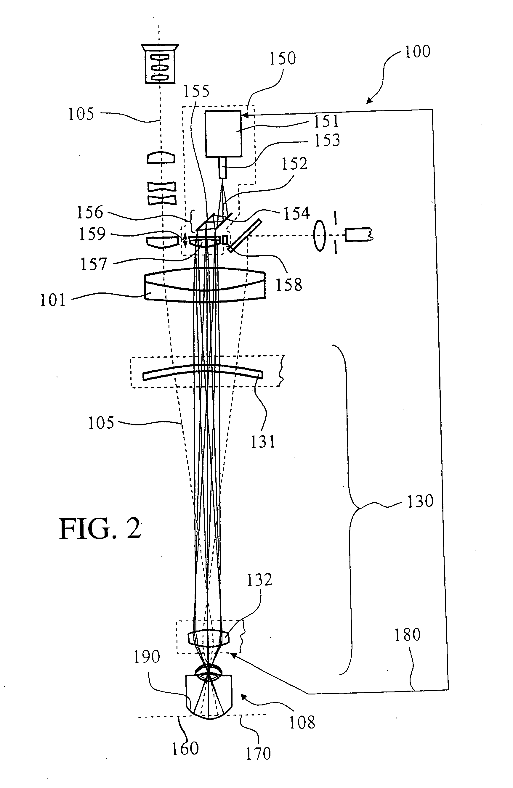
[0028]The surgical microscope 100 in FIG. 1 has a microscope main objective 101 defining an optical axis 102 as well as a focal plane 103. Stereoscopic viewing beam paths 105 of a binocular tube 106 pass through the microscope main objective 101.

[0029]The surgical microscope 100 has an illumination unit in the form of an illumination module 120 for illuminating the object region in the form of a patient eye 108. This illumination module 120 includes a first light conductor 121 which makes illuminating light 122 available from a light source (not shown). A displaceable field diaphragm 124 is illuminated by the illuminating light 122 exiting from the light conductor 121. A path-folding mirror 123 is mounted on the side of the microscope main objective 101 facing away from the object. The illuminating light exiting from the light conductor 121 is directed via path-folding mirror 123 through the microscope main objective 101 and into the object region 108.

[0030]An opthalmoscopic ancilla...


PUM


Abstract

An ophthalmic surgical microscope (100) has a microscope main objective (101) and a viewing beam path (105) which passes through the microscope main objective (101) for visualizing an object region. The ophthalmic surgical microscope (100) includes an OCT-system (140) for recording images of the object region (108). The OCT-system (140) includes an OCT-scanning beam (142) which is guided via a scan mirror arrangement (146) to the object region (108). An optic element (147) is provided between the scan mirror arrangement (146) and the microscope main objective (101). This optic element (147) bundles the OCT-scanning radiation exiting from the scan mirror arrangement (146) and transfers the same into a beam path which passes through the microscope main objective (101). Alternatively or in addition, the ophthalmic surgical microscope (100) includes an opthalmoscopic magnifier lens (132) which can be pivoted into and out of the viewing beam path (105) and the OCT-scanning beam (142).

Description

CROSS REFERENCE TO RELATED APPLICATIONS[0001]This application is a divisional application of U.S. patent application Ser. No. 11 / 984,819, filed Nov. 21, 2007, and claims priority of German patent application no. 10 2007 019 680.8, filed Apr. 24, 2007, the entire contents of which are incorporated herein by reference.FIELD OF THE INVENTION[0002]The invention relates to an ophthalmic surgical microscope having a microscope main objective and a viewing beam path which passes through the microscope main objective. The ophthalmic surgical microscope further includes an OCT-system for recording images of an object region. The OCT-system includes an OCT-scanning beam which is guided via a scan mirror unit to the object region.BACKGROUND OF THE INVENTION[0003]A surgical microscope of the kind referred to above is known from U.S. Pat. No. 6,004,314. This surgical microscope includes an OCT-system which generates a scanning beam of short coherent laser radiation. The OCT-system includes an an...

Claims


Application Information

Patent Timeline
Patent Type & Authority Applications(United States)
IPC IPC(8): G01B11/02
CPCA61B3/102A61B3/13A61B19/5223G02B21/0028G02B21/0032G01B9/02091G02B21/008G01B9/02007G01B9/02027G01B9/02035G02B21/0036A61B90/20
Inventor REIMER, PETERHAUGER, CHRISTOPHABELE, ALFONSSEESSELBERG, MARKUS
Owner CARL ZEISS MEDITEC AG
Learn More