Method of manufacturing piezoelectric vibrator, piezoelectric vibrator, oscillator, electronic device, and radio clock

a manufacturing method and technology of piezoelectric vibrators, applied in the direction of generators/motors, natural mineral layered products, cellulosic plastic layered products, etc., can solve the problems of not disclosing a specific manufacturing method of piezoelectric vibrators, impaired piezoelectric vibrators, etc., to improve the quality of the oscillator, improve the reliability of operation, and ensure the effect of air tightness

Inactive Publication Date: 2010-12-09
SEIKO INSTR INC
View PDF1 Cites 7 Cited by
  • Summary
  • Abstract
  • Description
  • Claims
  • Application Information

AI Technical Summary

Benefits of technology

[0055]The oscillator, the electronic device, and the radio clock according to the invention each include the high-quality piezoelectric vibrator that has reliable airtightness in the cavity and improved reliability of operation. Accordingly, likewise, it may also be possible to improve the quality of the oscillator, the electronic device, and the radio clock by improving the reliability of operation.
[0056]According to the piezoelectric vibrator of the invention, it may be possible to obtain a high-quality two-layer structure type surface mounted piezoelectric vibrator that can reliably maintain airtightness in a cavity and secure stable electric conduc...

Problems solved by technology

In particular, if the conductive member insufficiently comes into close contact with the through hole 204, there is a concern that the airtightness in the cavity C is impaired.
However, Patent Citations 1 and 2 disclose th...

Method used


Image

  • Method of manufacturing piezoelectric vibrator, piezoelectric vibrator, oscillator, electronic device, and radio clock
  • Method of manufacturing piezoelectric vibrator, piezoelectric vibrator, oscillator, electronic device, and radio clock
  • Method of manufacturing piezoelectric vibrator, piezoelectric vibrator, oscillator, electronic device, and radio clock

Examples


Embodiment Construction

[0082]An embodiment of the invention will be described below with reference to FIGS. 1 to 17.

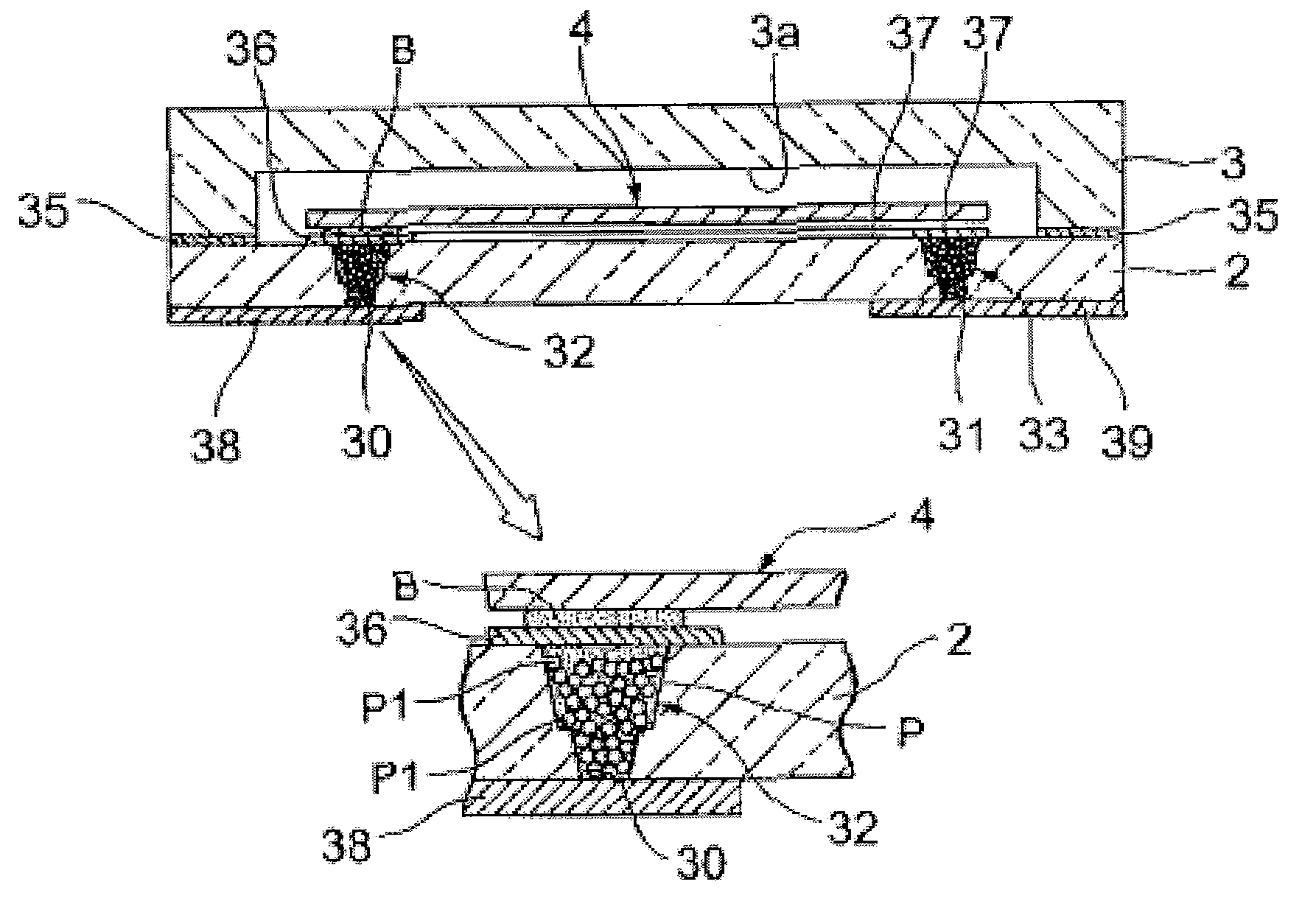
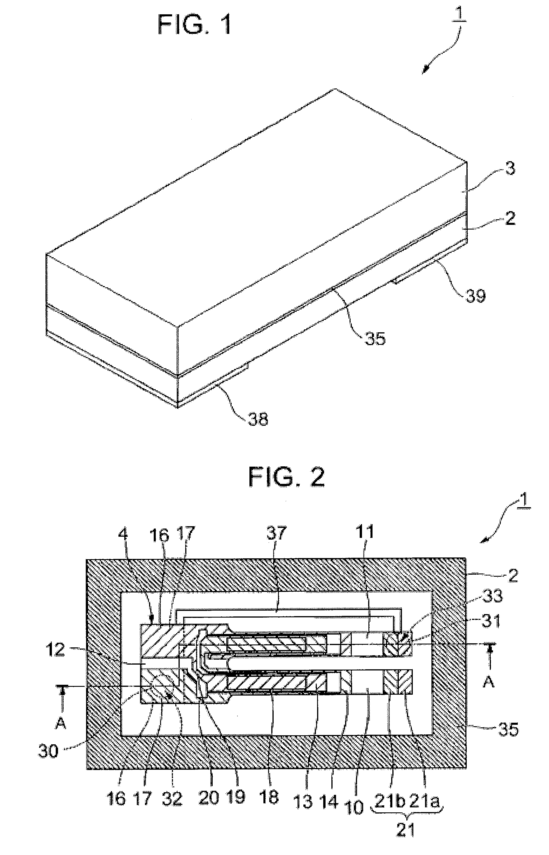
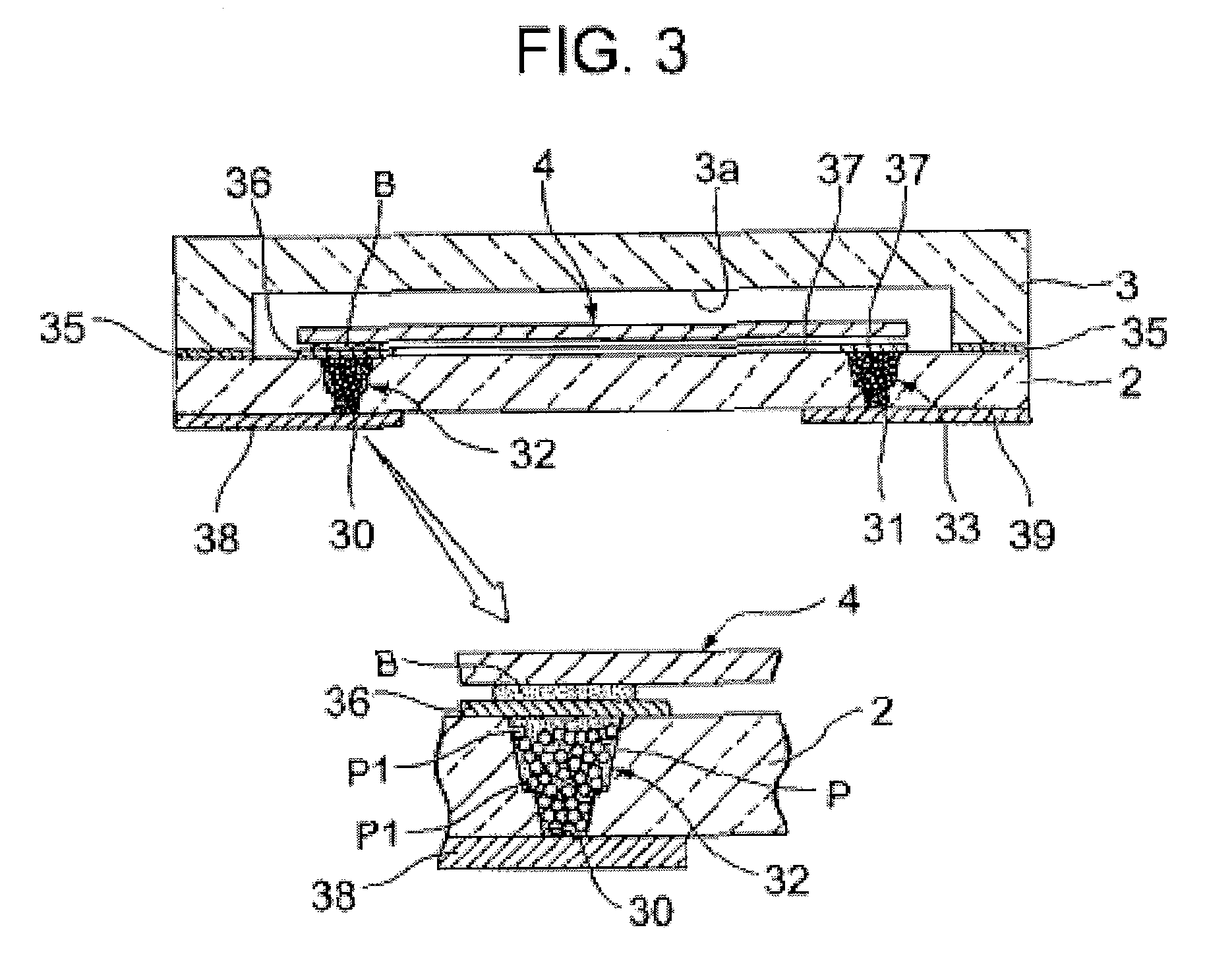
[0083]As shown in FIGS. 1 to 4, a piezoelectric vibrator 1 according to this embodiment is formed in a box shape where two layers (a base substrate 2 and a lid substrate 3) are laminated, and is a surface mounted piezoelectric vibrator 1 where a piezoelectric vibrating reed 4 is received in an inner cavity C.

[0084]Meanwhile, for the easy understanding of drawings, an excitation electrode 15, extraction electrodes 19 and 20, mount electrodes 16 and 17, and a weight metal film 21, which are to be described below, are not shown in FIG. 4.

[0085]As shown in FIGS. 5 to 7, the piezoelectric vibrating reed 4 is a tuning-fork type vibrating reed that is made of a piezoelectric material, such as crystal, lithium tantalite, or lithium niobate. When a predetermined voltage is applied to the piezoelectric vibrating reed, the piezoelectric vibrating reed vibrates.

[0086]The piezoelectric vibrating reed 4 i...


PUM

PropertyMeasurementUnit
Diameteraaaaaaaaaa
Diameteraaaaaaaaaa
Temperatureaaaaaaaaaa

Abstract

There is provided a piezoelectric vibrator 1 that includes a base substrate 2, a lid substrate 3, a piezoelectric vibrating reed 4, a pair of external electrodes 38 and 39, a pair of through electrodes 32 and 33, and routing electrodes 36 and 37. The lid substrate 3 includes a recess 3a for a cavity and is bonded to the base substrate so that the recess faces the base substrate. The piezoelectric vibrating reed 4 is bonded to the upper surface of the base substrate so as to be received in a cavity that is formed between both the substrates. The pair of external electrodes 38 and 39 is formed on the lower surface of the base substrate. The pair of through electrodes 32 and 33 is formed by hardening paste P, which contains a plurality of metal fine particles and a plurality of metal beads P1, so as to pass through the base substrate, maintains airtightness in the cavity, and is electrically connected to the pair of external electrodes, respectively. The routing electrodes 36 and 37 are formed on the upper surface of the base substrate and electrically connect the pair of through electrodes to the piezoelectric vibrating reed. The melting point of the metal bead is higher than the firing temperature of the paste.

Description

RELATED APPLICATIONS[0001]This application is a continuation of PCT / JP2008 / 072620 filed on Dec. 12, 2008, which claims priority to Japanese Application No. 2008-036420 filed on Feb. 18, 2008. The entire contents of these applications are incorporated herein by reference.BACKGROUND OF THE INVENTION[0002]1. Field of the Invention[0003]The present invention relates to a surface mounted (SMD) piezoelectric vibrator where a piezoelectric vibrating reed is sealed in a cavity formed between two bonded substrates, a method of manufacturing the piezoelectric vibrator, and an oscillator, an electronic device, and a radio clock that each include the piezoelectric vibrator.[0004]2. Description of the Related Art[0005]In recent years, a piezoelectric vibrator, which employs crystal or the like as a time source, a timing source of a control signal or the like, a reference signal source or the like, has been used in a cell phone or a portable information terminal device. Various piezoelectric vibr...

Claims


Application Information

Patent Timeline
IPC IPC(8): H01L41/053H01L41/22H01L23/02H01L23/12H03B5/32H03H3/02H03H9/02H03H9/10
CPCH01L23/055Y10T29/42H01L2924/09701H01L2924/3011H03H9/0519H03H9/0542H03H9/1021H03H9/21H01L2924/0002H01L2924/01079Y10T29/49005Y10T29/49165Y10T428/2982H01L2924/00
Inventor NUMATA, MASASHIARATAKE, KIYOSHI
Owner SEIKO INSTR INC
Why Eureka
Try Eureka