
Project Management Tool

a project management and tool technology, applied in the field of project management tools, can solve the problems of introducing limitations that are present in current project management implementations, team members are not able to assess tasks and provide direct input into master project plans, and achieve the effect of improving project timescale and budg

Inactive Publication Date: 2010-12-02
GASCONEX
View PDF31 Cites 47 Cited by
  • Summary
  • Abstract
  • Description
  • Claims
  • Application Information

AI Technical Summary

Benefits of technology

[0034]Using the generic system it will be possible to extend the functionality and develop several versions of the software tailored for each industry. Therefore two different systems could be developed for the software and engineering industries based off the generic base system.
[0035]The current invention provides for a new project management tool that allows complex projects to be managed, controlled, and visualized in such a way that each person in the project sees precisely the information that they require, to operate most effectively within the project. So, in contrast to the static Gannt chart, the current invention provides for a dynamic display of information, that changes depending on who is viewing the information, as well as the status of the project.
[0041]This project management system is particularly (but not exclusively) useful in the design of an engineered item. The proper oversight of the project permitted by the invention allows a more optimal design to be arrived at, and can also improve the project timescale and budget.
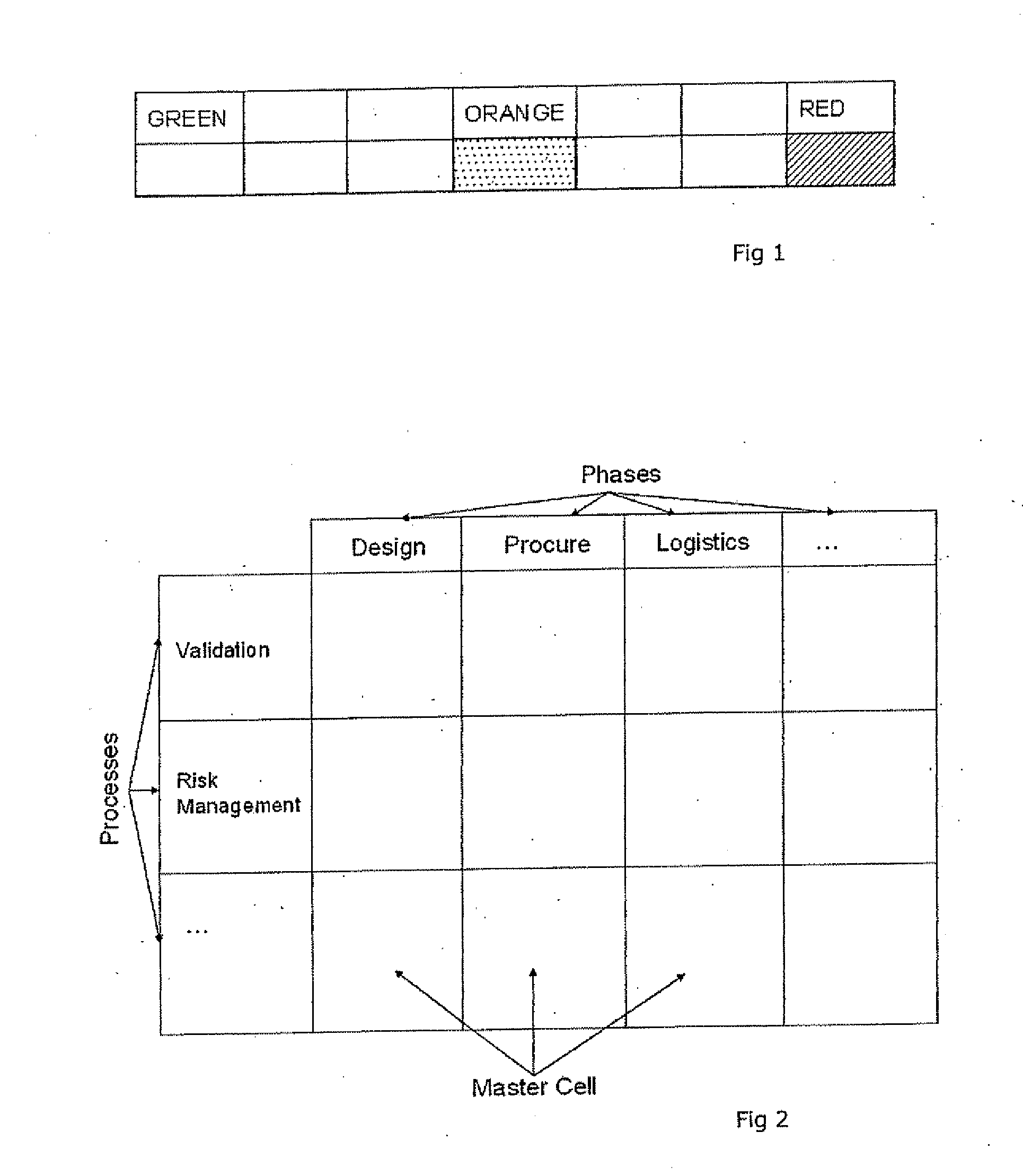
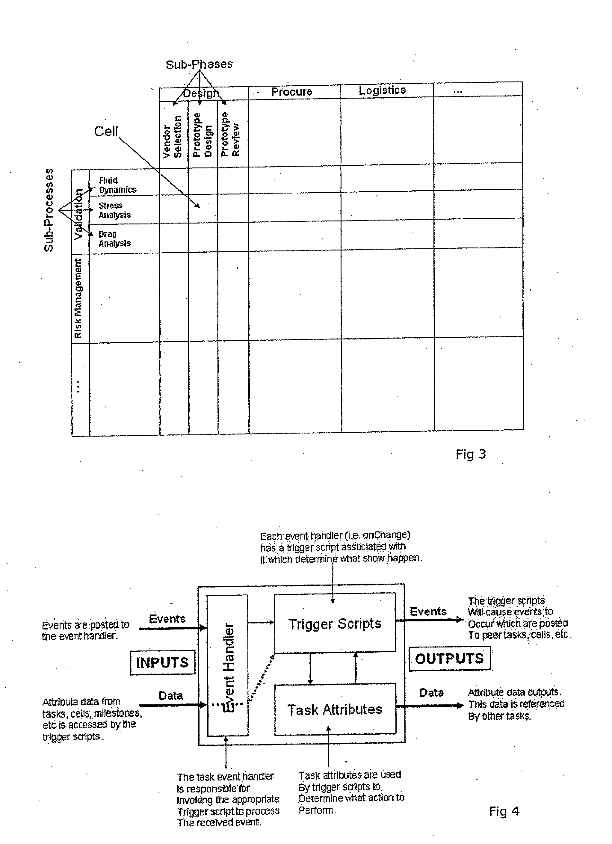
[0042]The phase definitions and process definitions can be grouped into phase classes and process classes respectively, to create a higher level view at which potentially distracting detail is removed. This allows more senior management, who may have oversight of more than one project, to see the project status and identify which projects and / or parts of projects require attention. Accordingly, the display means is preferably able to display a two-dimensional grid arrangement in which a first dimension is subdivided according to process classes and a second dimension is subdivided according to phase classes, thereby to define a plurality of cell groups at the intersection of the two dimensions, a plurality of the cell groups thus defined therefore representing a plurality of tasks, in respect of which a composite task status information is displayed.
[0048]Unlike known systems, the present invention provides an inherited system rather than a generic project management tool; the approach is to identify a base system common to all industries and provide a flexible and extensible or scalable approach for the system to be tailored to and effectively manage industry and company specific implementation standards and requirements.

Problems solved by technology

Several issues exist in relation to this type of system, particularly:1. Quality control is not enforced; tasks can be started / completed without quality control guidelines being adhered to, and with no tracking.2. The project manager is required to track all tasks manually and then manually update the system.3. A Gantt chart ‘only’ shows a real time estimation once the project manager has completed the update of each task's status estimation—typically on a weekly basis.4. There is no audit trail to track issues / questions / discussions / etc for each task.5. It is difficult for project managers to have a clear overview of how medium / large scale projects are performing, simply due to the number of tasks and their dependencies.6. Team members working on a project may not have a clear understanding of where their assigned tasks fit in with regards to the entire project.
Team members are not able to assess tasks and provide direct input into the master project plan.
This list is by no means comprehensive, but it does introduce some of the limitations that are present with current project management implementations.
Comparing projects from different industries highlights compatibility issues with regards to how the system will incorporate the necessary functionality.

Method used


Image

  • Project Management Tool
  • Project Management Tool
  • Project Management Tool

Examples


example 1

Software Development Life Cycle

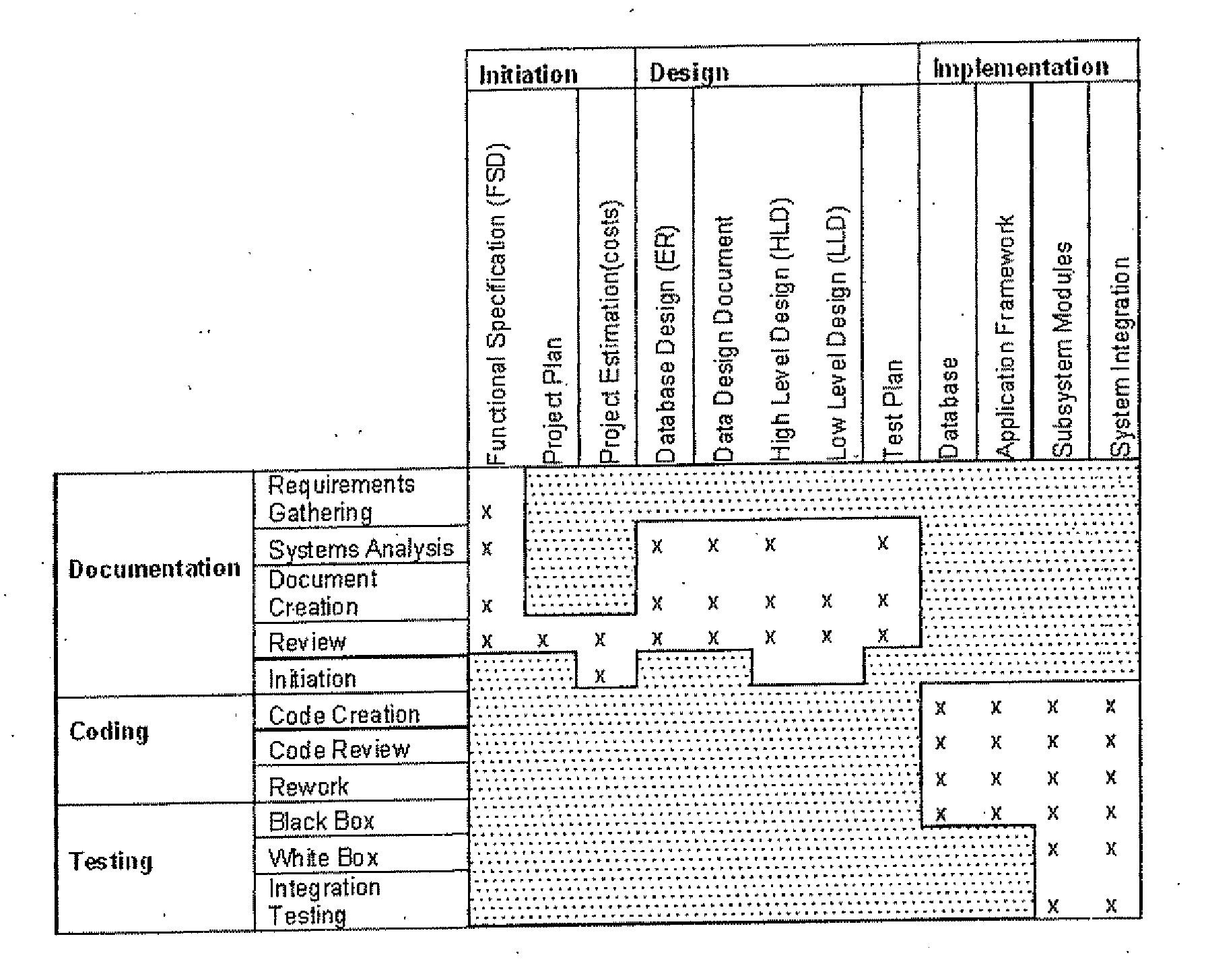
[0111]A company wishes to design and implement a ‘Killer’ Application. There are many design models for representation of the various process phases involved which require project management. Most of these approaches to process mapping are based or evolved from the traditional Waterfall view and the phases are essentially as follows (Note—variations may be found in the literature which in effect sub-divide or aggregate the phases listed here):[0112]1) Requirement Analysis[0113]2) Design[0114]3) Implementation[0115]4) Verification[0116]5) Review and Maintenance

[0117]Theses are illustrated schematically in FIG. 6.

[0118]This approach is a design method and its adoption has been superseded by more iterative approaches to complete lifecycle process. An example from IBM deriving from the Rational Software Company (www.rational.com) provides guidelines, templates and tools. It covers requirements, design, testing, project management and configuration manageme...

example 2

Building Construction Project

[0211]The following example is a simplistic view of a dwelling construction here we see the process distribution within the project map has a more uniform spread this is because:

[0212]The reason this seems to work for the construction example above is two fold:[0213]1. Construction projects have very similar high level Processes (foundations, services, floor slabs, walls etc.) even for projects as diverse as schools, dwellings or factories etc.[0214]2. Each of the Processes in the project have very real similarities in their phases, i.e. setting out the services, is almost identical to setting out the footings or the walls, and preparing shuttering for walls is the same as for columns or floors.

[0215]On closer examination, the issues for the software engineering project would also exist for the construction project if a higher level view was taken, and the construction design phases were also included within the project. In fact, this is one of the funda...


PUM


Abstract

A project management system comprises a means for storing each of a plurality of process definitions, a plurality of phase definitions, a plurality of task definitions, an association between each task definition and a selected process definition and a selected phase definition, and task status information associated with each task, and a display means for displaying a two-dimensional grid arrangement in which a first dimension is subdivided according to process definitions and a second dimension is subdivided according to phase definitions, thereby to define a plurality of cells at the intersection of the two dimensions, a plurality of the cells thus defined therefore representing tasks, in respect of which task status information is displayed.; A means for storing user identities and user rights associated with the user identities will allow the display means to be adapted to limit the display according to the user rights, either by withholding information relating to processes and / or phases not defined in the user rights, and / or by aggregating a plurality of cells and displaying a composite task status. This project management system is preferably provided via a suitable computer system, and a software module is arranged to implement this. Further, a project management summary view can comprise a two-dimensional grid arrangement in which a first dimension is subdivided according to processes and a second dimension is subdivided according to phases of work, thereby to define a plurality of cells at the intersection of the two dimensions, a plurality of the cells representing tasks in respect of which task status information is displayed. This project management system is particularly (but not exclusively) useful in the design of an engineered item. The proper oversight of the project permitted by the invention allows a more optimal design to be arrived at, and can also improve the project timescale and budget.

Description

[0001]This Application is a Section 371 National Stage Application of International Application No. PCT / EP2008 / 002959, filed Sep. 1, 2008 and published as WO 2009 / 027709 A9 on Mar. 5, 2009, the content of which is hereby incorporated by reference in its entirety:FIELD OF THE INVENTION[0002]The present invention relates to a project management tool.BACKGROUND ART[0003]The current invention relates to the management of technical design projects. When a project is small, simple and fast, there is little need for specialized methods of project management. However, for larger more complex projects, that take place over longer periods of time, many issues arise, and the management of the project becomes critical to the success of the project.[0004]In such projects, effective management is essential and will have a material effect on the final technical design. Poor management will produce a result that is late and / or over budget, but is also likely to produce a materially different design...

Claims


Application Information

Patent Timeline
Patent Type & Authority Applications(United States)
IPC IPC(8): G06Q10/00
CPCG06Q10/06G06Q10/067G06Q10/06313
Inventor GASKELL, PETER JOHN AYRTON
Owner GASCONEX
Learn More