
Ground-Coupled Heat Exchange for Heating and Air Conditioning Applications

a heat exchange and ground-coupled technology, applied in the field of ground-coupled thermosiphons, can solve the problems of high energy consumption, frequent energy intensive and cost prohibitive, and the system can cost on the order of thousands of dollars for residential systems, and even more for commercial spaces, and achieve the effect of cost saving and minimal energy requirements

Inactive Publication Date: 2010-12-02
UNIV OF UTAH RES FOUND
View PDF10 Cites 39 Cited by
  • Summary
  • Abstract
  • Description
  • Claims
  • Application Information

AI Technical Summary

Benefits of technology

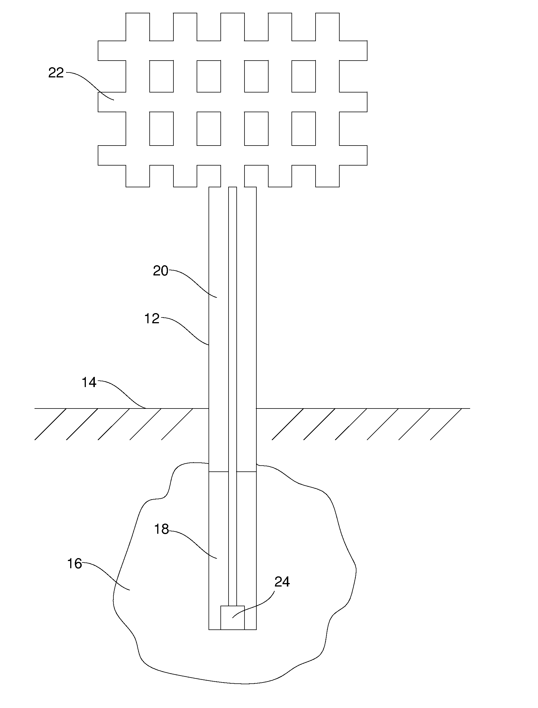
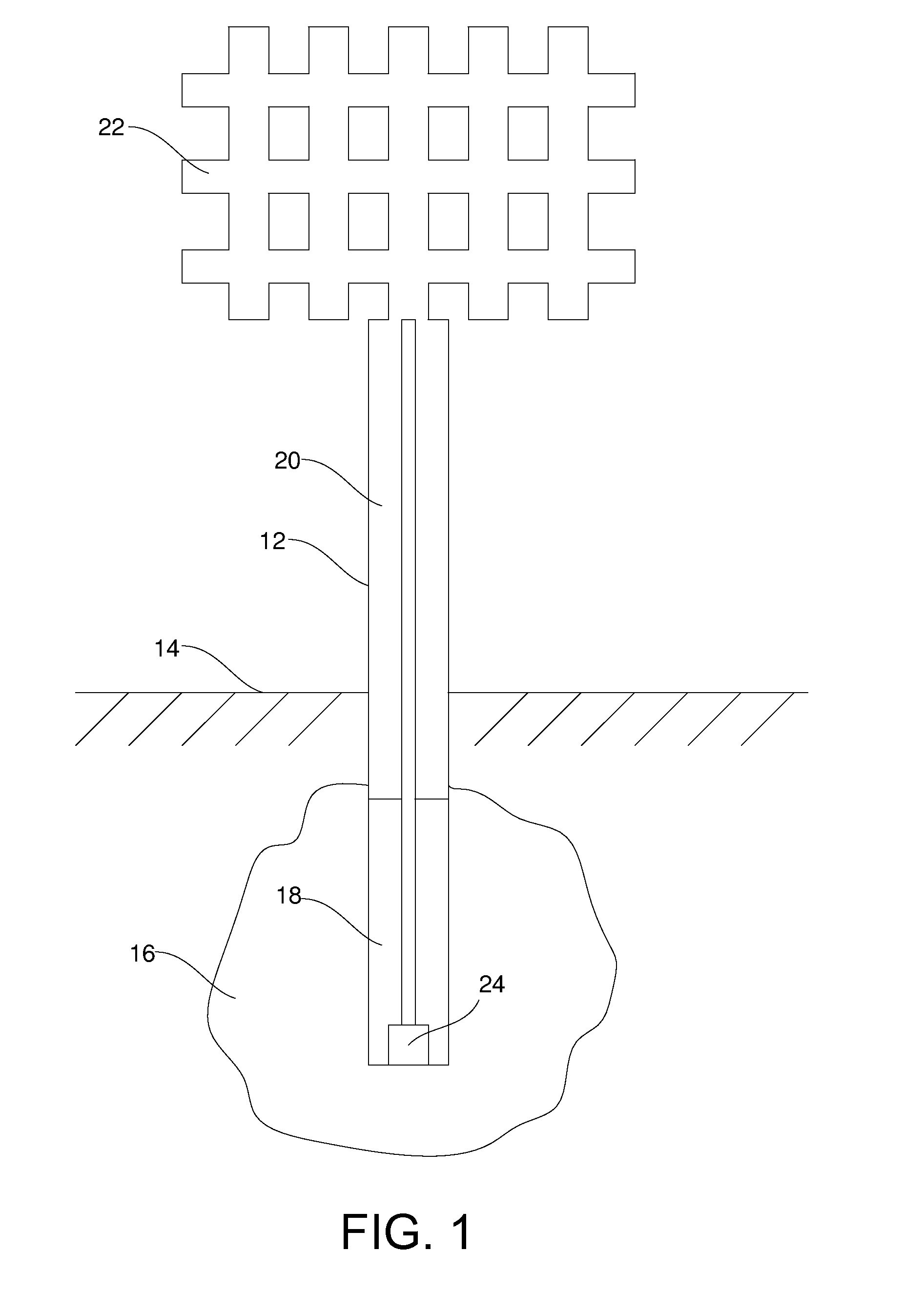
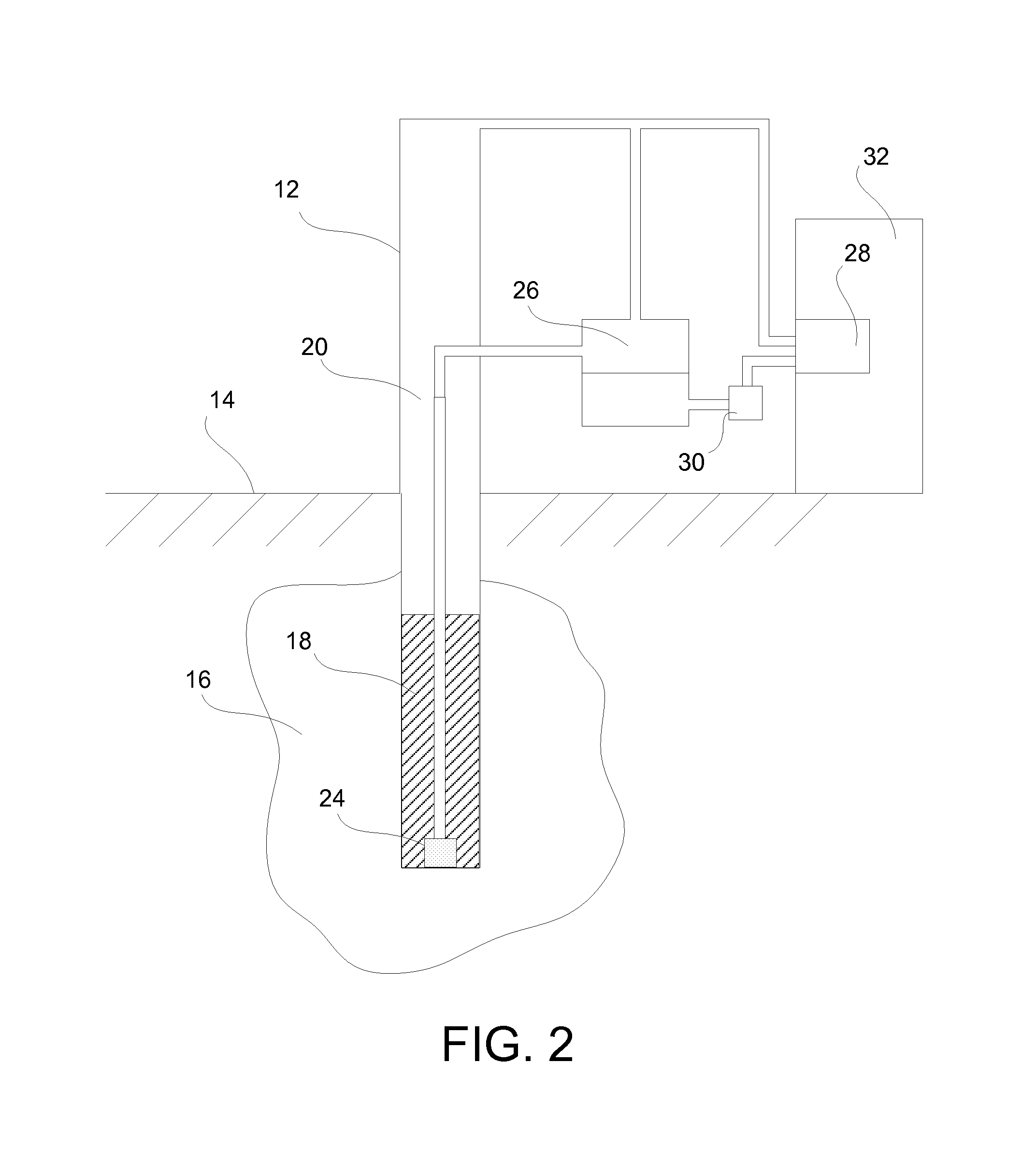
[0006]It has been recognized that it would be advantageous to develop a heating and air-conditioning system with minimal energy requirements which is also cost effective. In one embodiment, a system for heating or cooling a structure can include a thermosiphon in thermal communication with a thermal storage material. The thermosiphon can be partially filled with a heat transfer fluid such that both liquid and vapor phases are present. A heat exchanger can be operatively connected to the thermosiphon and be in thermal communication with the structure such that thermal energy can be transferred between the thermal storage material and the structure. A fluid transfer device can be fluidly associated with the heat transfer fluid and configured to draw the heat transfer fluid towards the heat exchanger.

Problems solved by technology

Heating and air conditioning systems are needed throughout the world but are frequently energy intensive and cost prohibitive.
Such systems can typically cost on the order of thousands of dollars for residential systems, and even more for commercial spaces.
Additionally, they generally require a great deal of energy to obtain satisfactory performance adding to the cost and further burdening the energy resources of communities.
Other costs associated with such systems include filters, regular maintenance, and replacement of expensive parts, e.g., compressors.
However, these systems require constant pumping of fluids through the system and have non-optimal heat transfer coupling between the pipes and surround soil.
Further, vertical borehole systems utilize adjacent hot and cold tubes which results in some short-circuiting of heat and reduction in efficiencies.
At the present time, the development of improved heating and cooling systems, by either improving existing systems or discovering new materials that meet all desirable requirements for practical applications, remains a complex and challenging task.

Method used


Image

  • Ground-Coupled Heat Exchange for Heating and Air Conditioning Applications
  • Ground-Coupled Heat Exchange for Heating and Air Conditioning Applications
  • Ground-Coupled Heat Exchange for Heating and Air Conditioning Applications

Examples


example 1

Heat Load Calculation for a Typical Residential House in Utah

[0053]The available solar energy in Utah is about 1670 kW-hr / m2 / year. Such solar energy at a 70% solar collector efficiency would be about 1169 kWh / m2 / year or 4.2 GJ / m2 / year. The solar energy was calculated using a solar constant 1.370 kW / m2, annual average of 4.6 kWh / m2 / day, monthly average (min in December) of 1.7 kWh / m2 / day, and monthly average (max in June) of 7.4 kWh / m2 / day.

[0054]The following tables represent heating and cooling load calculations based on Salt Lake City, Utah data.

TABLE 1Heating and Cooling Load Calculation -Ground-Source Heat Pump ProjectEstimateSite ConditionsNearest location for weather dataSalt LakeCity, UTHeating design temperature° C.−11.5Cooling design temperature° C.35.1Average summer daily temperature range° C.15.0Cooling humidity level—MediumLatitude of project location° N40.8Mean earth temperature° C.12.0Annual earth temperature amplitude° C.15.0Depth of measurement of earth temperaturem3....

example 2

Thermal Energy Storage Dimensions for One Family House (Simplified Calculation)

[0056]Energy recovery efficiency for underground thermal energy storage can be calculated using the dimensions of a soil cylinder holding annual energy load of a typical one family residential house (150 m2×2 floors+basement). This calculation uses the energy calculations from Example 1 (QCooling=82×109 J, QHeating=29×109 J) and assumes the following characteristics of the soil cylinder: ηE=0.60, ΔT=15° C., H=10 m, ρcp≈2×10⁶ J / m3° C. (damp soil). Using the following equation:

Qout=ηEQin=ηEHπR2ρcpΔT

the results estimate the RCooling at about 9.3 m and the RHeating at about 7.2 m. The present calculation shows the feasibility of the structures described herein. Of course, the final dimensions would depend on the specific soil, environment, and heating / cooling demands needed.

example 3

[0057]As an example, the performance of a set of 7 thermosiphons for freezing soils and the use of frozen soil as an air conditioning heat sink was assessed using a two-dimensional model discussed below. A preliminary model of freezing and thawing of water-saturated soil was created using the commercially available software package COMSOL Multiphysics 3.3. The geometry chosen for the analysis was an array of six thermosiphons placed at the corners of a symmetrical hexagon with a seventh thermosiphon placed at the center of the hexagon. Utilizing the symmetry of the system, a quarter circle with a 5-meter radius was chosen as the domain of interest. Three thermosiphons were modeled in this domain: one positioned centrally and the other two placed 60 degrees apart with one of them on the axis of symmetry. The spacing between thermosiphons was 1.5 meters. Only conduction was modeled in this basic rendition.

[0058]An ambient temperature model was used for the external temperatures. This ...


PUM


Abstract

The invention provides systems and methods for cooling and / or heating a structure. Generally, a system for heating or cooling a structure can include at least one thermosiphon in thermal communication with a thermal storage material such as a volume of earth. The thermosiphon can be partially filled with a heat transfer fluid and a heat exchanger operatively connected to the thermosiphon which is in thermal communication with the structure. Thermal energy can be transferred between the thermal storage material and the structure in either a passive or assisted mode, depending on whether the system is charging or in use.

Description

FIELD OF THE INVENTION[0001]The present invention relates generally to ground-coupled thermosiphons. More particularly, the present invention relates to methods and systems of heating and cooling a structure using ground-coupled thermosiphons. As such, the present invention relates to the fields of geothermal engineering, thermodynamics, and material science.BACKGROUND OF THE INVENTION[0002]Heating and air conditioning systems are needed throughout the world but are frequently energy intensive and cost prohibitive. Such systems can typically cost on the order of thousands of dollars for residential systems, and even more for commercial spaces. Additionally, they generally require a great deal of energy to obtain satisfactory performance adding to the cost and further burdening the energy resources of communities. Generally, heating and cooling costs can run upwards of 75% of a building's total utility cost annually and by some estimates account for upwards of 45% of total energy usa...

Claims


Application Information

Patent Timeline
IPC IPC(8): G06F17/50F28D15/02F28F13/00F24J3/08F25B29/00G06F17/10F24V50/00
CPCF24J3/081Y02E10/12F25B30/06F24T10/10F24T2201/00F24T10/40Y02E10/10
Inventor UDELL, KENT STEWART
Owner UNIV OF UTAH RES FOUND
Learn More