Operating method for fluid working machine

Active Publication Date: 2010-12-02
ARTEMIS INTELLIGENT POWER
View PDF13 Cites 7 Cited by
  • Summary
  • Abstract
  • Description
  • Claims
  • Application Information

AI Technical Summary

Benefits of technology

[0018]Therefore, it is the object of the invention to provide a fluid working machine and a method for operating a fluid working machine, causing less problems with fluid flow pulsations.
[0022]It is preferred, that at least the pumping / motoring fraction between 0% and 33.3% (one third) of the maximum pumping / motoring volume of said working chamber is chosen. In other words, the electrically actuated inlet valve is closed a relatively short time before the working chamber reaches its minimum volume. In fluid working machines of the piston and cylinder type this would be close to the top dead center. It has been discovered that closing the electrically actuated valve in other regions could lead to increased noise generation and to an increased wear of the electrically actuated valve. This is because of the sinusoidal change of the working chamber's volume in standard type fluid working machines. If the electrically actuated valve is closed in a region of a high change of the working chamber's volume, the speed of the hydraulic fluid entering and / or leaving the working chamber is accordingly high. Of course, it is still possible to actuate the electrically actuated valve outside of the mentioned region, particularly if other modes of noise attenuation an / or hardened valve heads and / or hardened valve seats are used. Furthermore it should be noted, that the mentioned numbers of 0 and 33.3% for the interval limits are not fixed numbers. Instead, also 5%, 10%, 15%, 20%, 25%, 30%, 35% and / or 40% could be used as upper / lower interval limits. In particular, as the upper / lower interval limit 1 / 3, 1 / 4, 1 / 5, 1 / 6, . . .(i.e.1NforN=3,4,…)can be advantageous as well. Of course, the mentioned interval can apply for one, a plurality of or all working chambers and / or for one, a plurality of or all pumping strokes of one, a plurality of or all working chambers.
[0023]Another preferred embodiment of the invention can be realised, if at least a pumping / motoring fraction between 66.7% (two thirds) and 100% of the maximum pumping / motoring volume of said working chamber is chosen. Once again, the mentioned numbers are not fixed numbers. Instead, 60%, 65%, 70%, 75%, 80%, 85%, 90% and / or 95% can be chosen as upper / lower interval limits as well. Likewise, 2 / 3, 3 / 4, 4 / 5, 5 / 6, . . .(i.e.N-1NforN=3,4,…)can be advantageous. In other words, the electrically actuated valve will be closed some time after the working chamber has reached its maximum volume and starts to shrink again. In hydraulic fluid working machines of the piston-and-cylinder type, this would be equivalent to a position at or shortly after leaving the bottom dead center. Once again, by selecting this interval, it can be possible to reduce the generated noise and to reduce the wear of the electrically actuated valves. However, it is still possible to vary the fluid-flow output according to the demand with very little pressure variations over a considerably large interval. The mentioned interval can be used for one, a plurality of or all working chambers and / or one, a plurality of or all pumping strokes of one, a plurality of or all working chambers.

Problems solved by technology

Admittedly, this may cause the problem that the real fluid flow output can only be approximated from the actuation time.

Method used


Image

  • Operating method for fluid working machine
  • Operating method for fluid working machine
  • Operating method for fluid working machine

Examples


Embodiment Construction

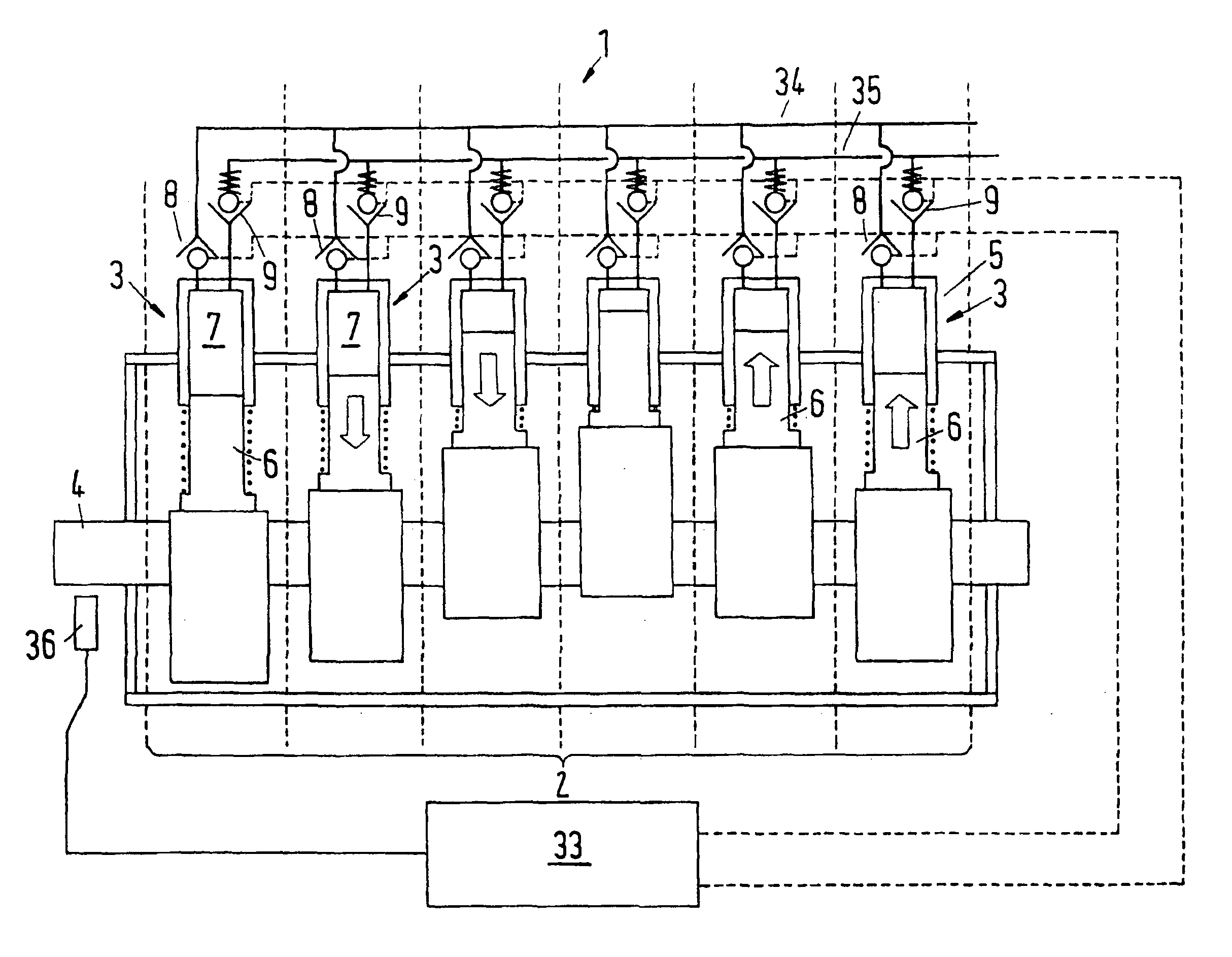
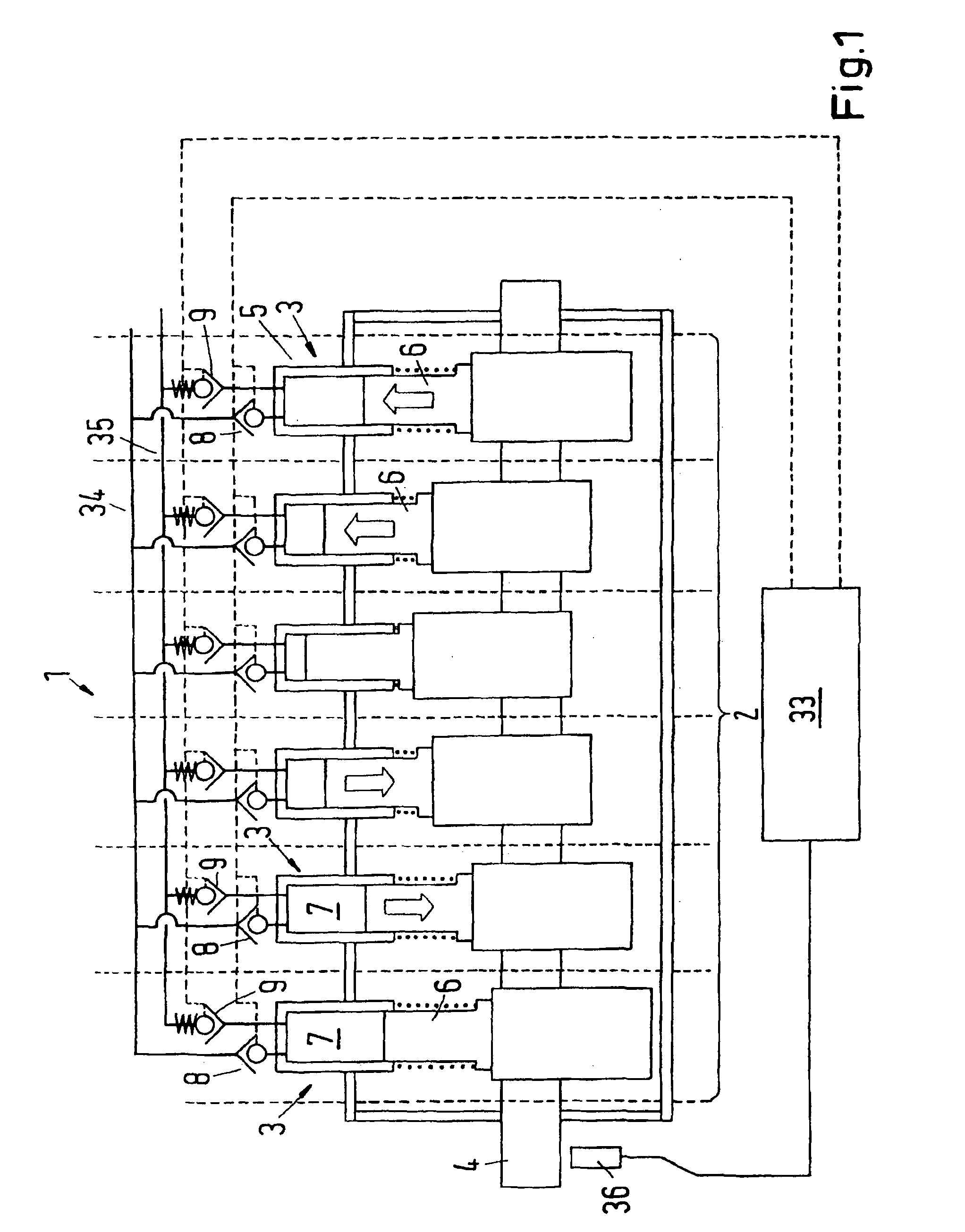
[0043]FIG. 1 shows the schematic overview of a synthetically commutated hydraulic pump, comprising one bank 2 with six cylinders 3. The cylinders 3 are connected to a single rotatable shaft 4, that is common to all cylinders 3. The cylinders 3 are comprising a cylinder portion 5 and a piston 6, each. As it is obvious from FIG. 1, due to the arrangement of the cylinders 3 in a radial direction, each cylinder 3 starts its working cycle at a different time during the rotation of the rotatable shaft 4, i.e. at a different angle of the rotatable shaft 4. In the present example, the six cylinders 3 are arranged at regular intervals. Therefore, the phase difference between two neighbouring cylinders 3 is 60%.

[0044]It has to be mentioned, that it is of course possible to use a different number of cylinders 3, i.e. four, five, seven or eight cylinders or any other integer number (it can be even or odd). Also, a different number of cylinder banks 2 may be provided. Furthermore, the cylinders ...


PUM


Abstract

A fluid working machine (1) has several working chambers (5) of cyclically changing volume. For pumping hydraulic fluid, the inlet and outlet valves (8, 9) are electrically actuated. The timing of the actuation of said electrically actuated valves (8, 9) is varied depending on the fluid flow demand.

Description

CROSS REFERENCE TO RELATED APPLICATIONS[0001]This application is entitled to the benefit of and incorporates by reference essential subject matter disclosed in International Patent Application No. PCT / DK2008 / 000381 filed on Oct. 29, 2008 and EP Patent Application No. 07254337.4 filed Nov. 1, 2007.FIELD OF THE INVENTION[0002]The invention relates to a method of operating a fluid working machine, comprising at least one working chamber of cyclically changing volume, a high pressure fluid connection, a low pressure fluid connection and at least one electrically actuated valve, connecting said working chamber to said high pressure fluid connection and / or said low pressure fluid connection. The invention further relates to a fluid working machine, comprising at least one working chamber of cyclically changing volume, a high pressure fluid connection, a low pressure fluid connection, at least one electrically actuated valve, connecting said working chamber to said high pressure fluid conn...

Claims


Application Information

Patent Timeline
IPC IPC(8): F04B7/00F04B39/08F04B49/22
CPCF04B7/0076F04B11/005F04B49/06F04B49/243F04B2201/0601F04B2205/13
Inventor KUTTLER, ONNOLAI, KEN KIN-HO
Owner ARTEMIS INTELLIGENT POWER
Why Eureka
Try Eureka