
Two-Layer Switch Apparatus To Avoid First Layer Inter-Switch Link Data Traffic In Steering Packets Through Bump-In-The-Wire Service Applications

a switch apparatus and data traffic technology, applied in the field of link-level data communication, can solve the problems of burdening additional headers, affecting the speed of data transmission,

Inactive Publication Date: 2010-12-02
IBM CORP
View PDF20 Cites 123 Cited by
  • Summary
  • Abstract
  • Description
  • Claims
  • Application Information

AI Technical Summary

Benefits of technology

[0010]The switching apparatus also includes a plurality of data communications ports. At least two of the ports couple the switching apparatus to at least two data communications networks, and at least two additional ports are connected to service applications on at least two of the modular computer systems that carry out transparent, bump-in-the-wire data processing of data communications packets traveling among the networks. Each service application is associated with a unique, link

Problems solved by technology

Since that time, computer systems have evolved into extremely complicated devices.
When data packets are to be processed by several service applications the problem of routing the data stream from one service application to another naturally arises.
This requirement to process this additional layer of headers is a burden to hardware developers and application providers who must now design, develop, test, and support an additional configuration of their core product.
This option changes the packet and limits the ability to perform the types of analysis that rely on possession of the original addresses in the packet.

Method used


Image

  • Two-Layer Switch Apparatus To Avoid First Layer Inter-Switch Link Data Traffic In Steering Packets Through Bump-In-The-Wire Service Applications
  • Two-Layer Switch Apparatus To Avoid First Layer Inter-Switch Link Data Traffic In Steering Packets Through Bump-In-The-Wire Service Applications
  • Two-Layer Switch Apparatus To Avoid First Layer Inter-Switch Link Data Traffic In Steering Packets Through Bump-In-The-Wire Service Applications

Examples


Embodiment Construction

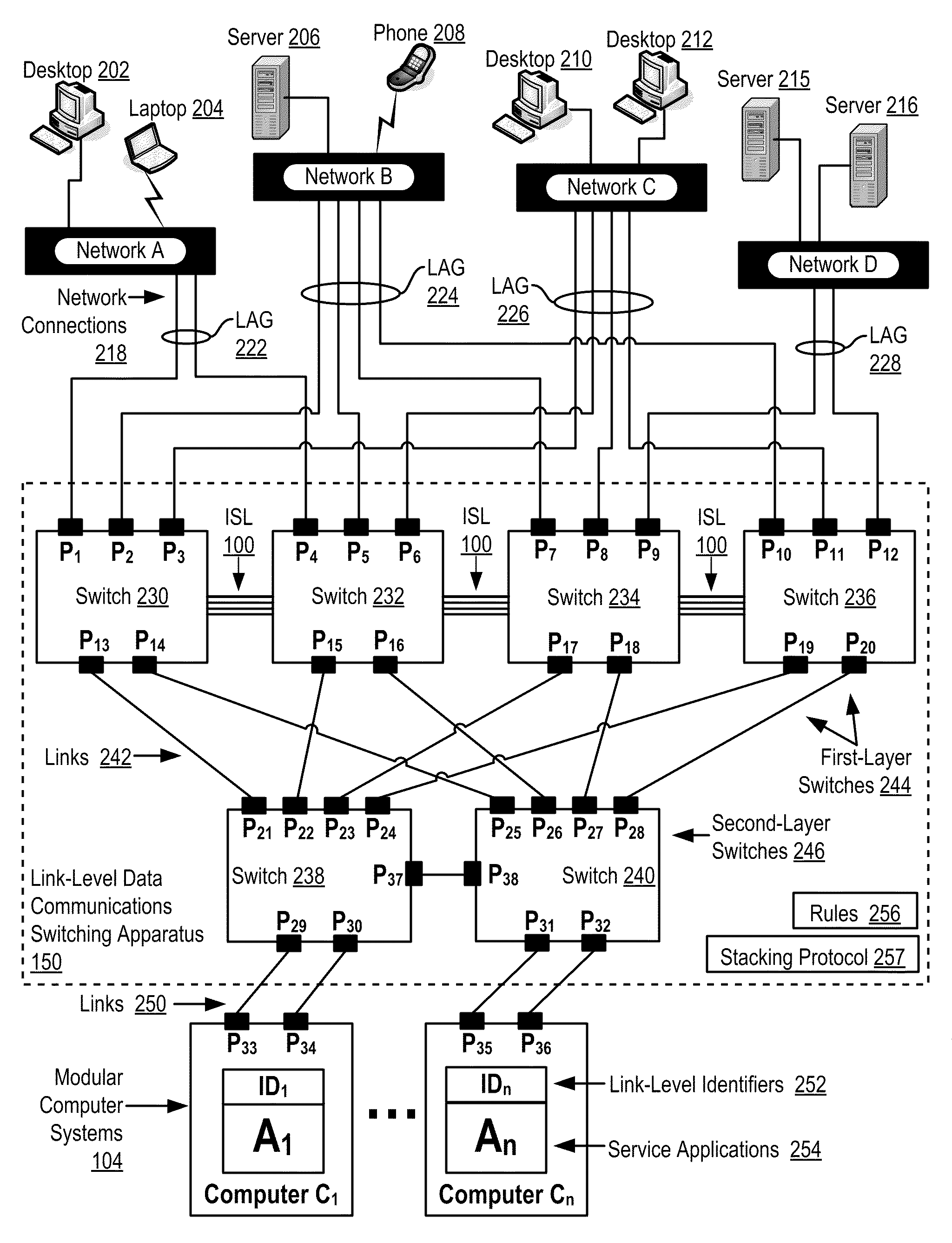
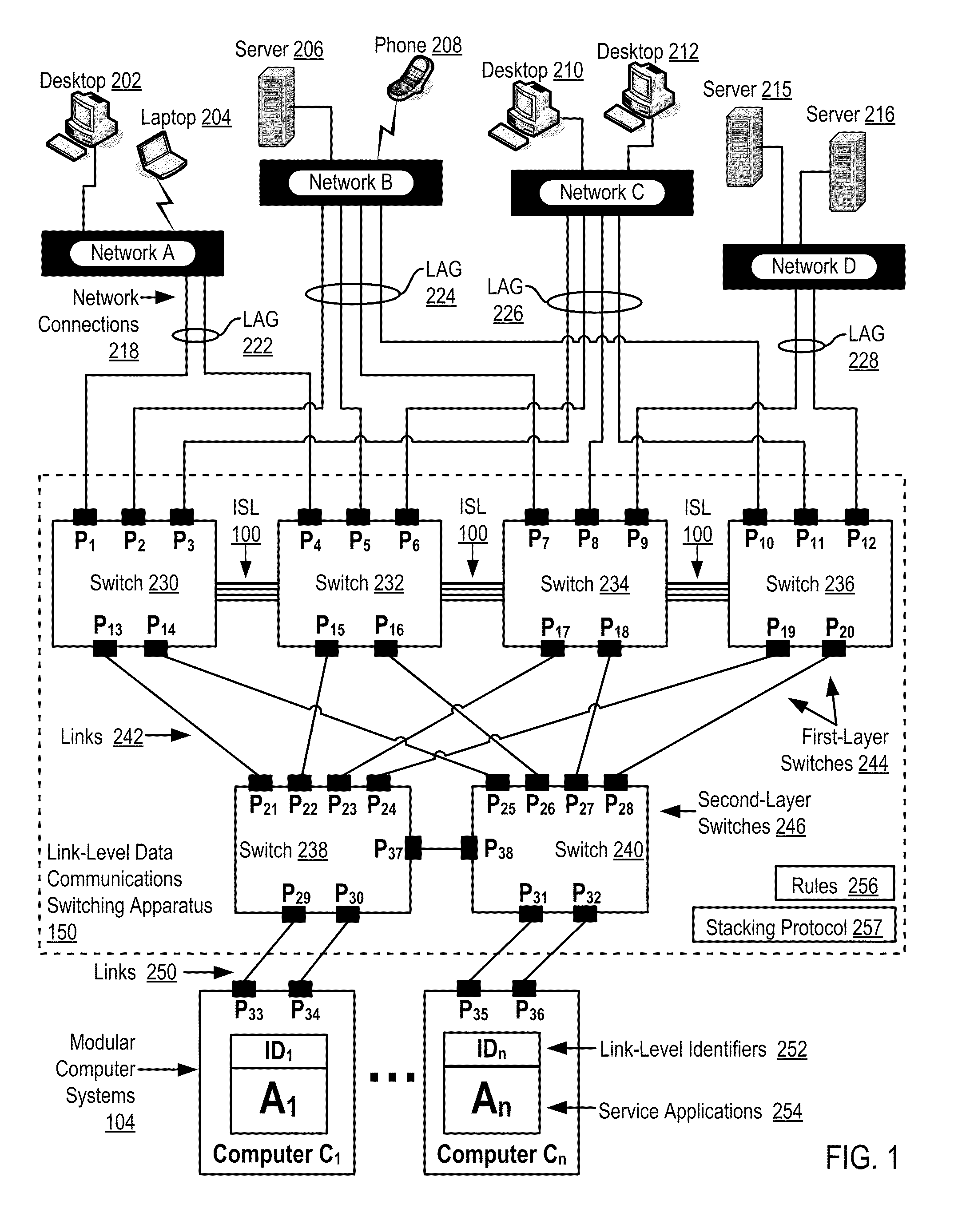
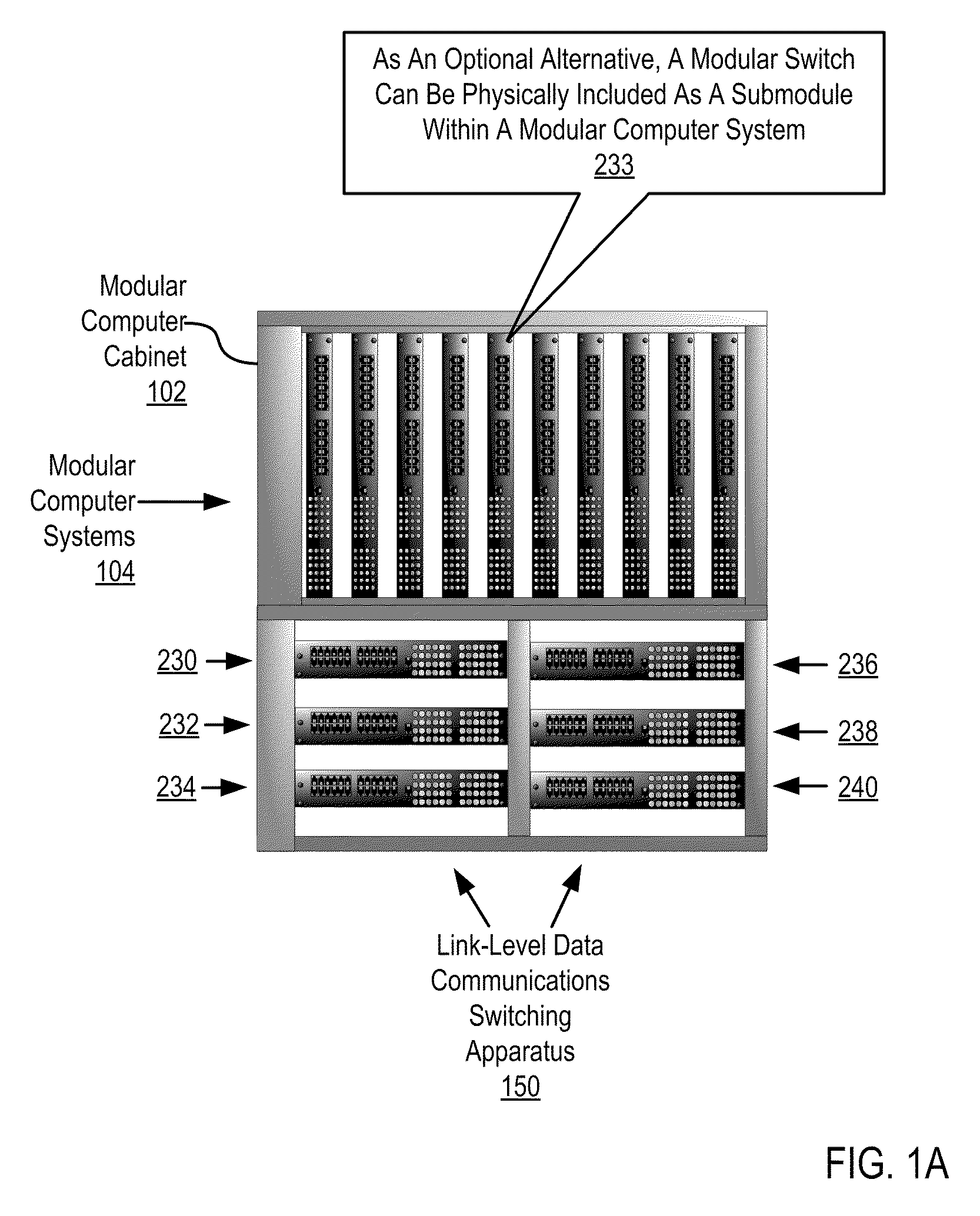
[0019]Example methods, apparatus, and products for link-level data communications in accordance with the present invention are described with reference to the accompanying drawings, beginning with FIG. 1. FIG. 1 sets forth a functional block diagram of automated computing machinery, example automated apparatus for link-level data communications according to embodiments of the present invention. The apparatus of FIG. 1 includes a link-level data communications switching apparatus (150) that includes modular link-level data communications switches (230, 232, 234, 236, 238, 240). The modular link-level data communications switches (230, 232, 234, 236, 238, 240) of FIG. 1 are disposed within a modular computer cabinet (102 on FIG. 1A) that also includes a plurality of modular computer systems (104) disposed within the modular computer cabinet. A modular computer cabinet is a frame or enclosure for mounting multiple computing devices. A modular computer cabinet may be embodied, for examp...


PUM


Abstract

Link-level data communications carried out in a link-level data communications switching apparatus that includes modular link-level data communications switches; the switching apparatus is configured as two layers of link-level data communications switches; all the switches stacked by a stacking protocol that shares administrative configuration information among the switches and presents the switches as a single logical switch; the switching apparatus includes data communications ports coupling the switching apparatus to data communications networks and to service applications, each service application associated with a unique, link-level identifier; the switching apparatus includes rules governing the steering of packets among service applications and networks; including receiving, in the switching apparatus, packets directed to a destination network; and steering each packet among the service applications to the destination network in accordance with the rules, without using the link-level identifier of any service application.

Description

BACKGROUND OF THE INVENTION[0001]1. Field of the Invention[0002]The field of the invention is data processing, or, more specifically, methods, apparatus, and products for link-level data communications.[0003]2. Description of Related Art[0004]The development of the EDVAC computer system of 1948 is often cited as the beginning of the computer era. Since that time, computer systems have evolved into extremely complicated devices. Today's computers are much more sophisticated than early systems such as the EDVAC. Computer systems typically include a combination of hardware and software components, application programs, operating systems, processors, buses, memory, input / output devices, and so on. As advances in semiconductor processing and computer architecture push the performance of the computer higher and higher, more sophisticated computer architectures have evolved to take advantage of the higher performance of the hardware, resulting in computer systems today that are much more p...

Claims


Application Information

Patent Timeline
IPC IPC(8): H04L12/56
CPCH04L49/602
Inventor BELANGER, MATTHEW T.SHIPPY, GARY R.
Owner IBM CORP
Learn More