
Wire feeder with auto-configure power supply

Active Publication Date: 2010-12-02
LINCOLN GLOBAL INC
View PDF8 Cites 32 Cited by
  • Summary
  • Abstract
  • Description
  • Claims
  • Application Information

AI Technical Summary

Benefits of technology

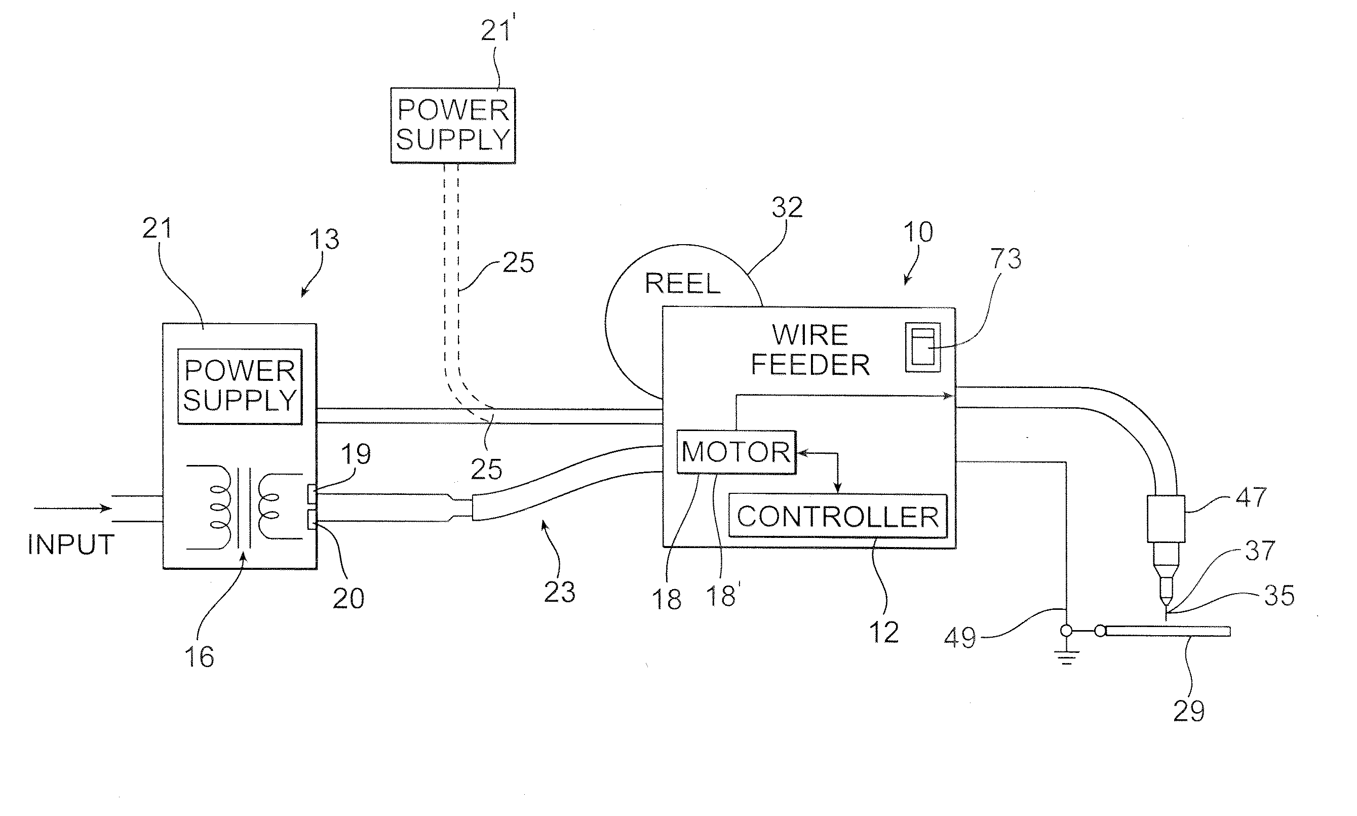
[0004]The embodiments of the present invention are directed to devices and methods of arc welding, including wire feeder drive systems that can be easily connected to receive power from different power sources and from different types of arc welders without having to significantly modify the wire feeder. The invention will be described with particular reference to wire feeders in association with MIG or TIG welders. However, it will be appreciated by persons of ordinary skill in the art that the embodiments described herein can be utilized in any type of welder requiring a continuous feed of wire. The wire feeder may include electrical circuitry that can detect and activate the wire drive system responsive to different sources of power as, for example, from a regulated power supply or from the welding arc.

Problems solved by technology

Other wire feeders draw power from a separate regulated power supply, since some applications require greater precision and may be adversely affected by power drawn from across the arc.

Method used


Image

  • Wire feeder with auto-configure power supply
  • Wire feeder with auto-configure power supply
  • Wire feeder with auto-configure power supply

Examples


Embodiment Construction

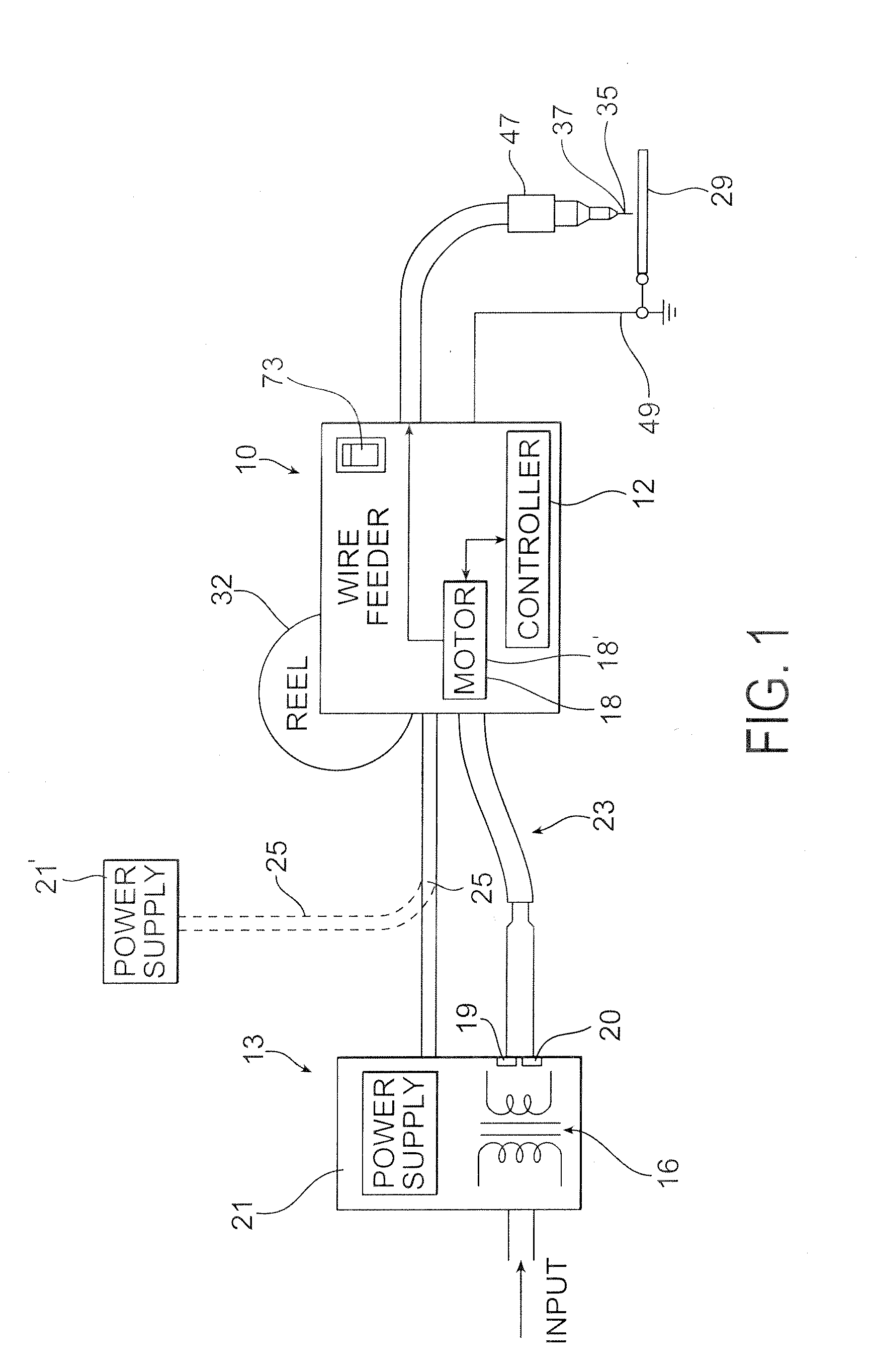
[0014]Referring now to the drawings wherein the showings are for purposes of illustrating embodiments of the invention only and not for purposes of limiting the same, FIG. 1 shows a wire feeder depicted generally at 10. The wire feeder 10 may be used in conjunction with a welding power source 13 as manufactured by, for example, the Lincoln Electric company in Cleveland, Ohio. The welding power source 13 may receive electrical input power from an outside source that is directed to a transformer 16 having primary and secondary windings in a manner well known in the art. Output from the secondary windings may be directed to a rectifier, not shown, providing DC supply power to the output terminals or studs 19, 20. It is noted that in an alternative embodiment, output power from the welding power supply may be supplied in the form of AC type power. The welding power source 13 may include a power controller, not shown, designed to control output power at the studs 19, 20. In one mode of o...


PUM

PropertyMeasurementUnit
Poweraaaaaaaaaa
Threshold limitaaaaaaaaaa

Abstract

A wire drive system includes a wire feed motor for feeding welding wire in a continuous welding process. The wire drive system further includes a controller connected to the wire feed motor for driving the motor responsive to a command signal. The controller is capable of detecting the source of power from which the wire feed motor is driven wherein a first possible source of power is taken from the welding arc and wherein a second possible source of power is taken from the welding power supply.

Description

TECHNICAL FIELD[0001]The present invention pertains to wire feeders for welding power supplies, and more particularly, to wire feeders that automatically switch between power sources.BACKGROUND OF THE INVENTION[0002]Wire feeders are commonplace in the field of welding. As is well known, they are used in conjunction with a welding power source for feeding a wire electrode to a workpiece during the welding process. The electrode may include solid wire, which in some instances is coated depending on the application. Other applications utilize flux cored wire. The wire is continuously fed at a rate which may vary during the welding process. Such processes include, for example, FCAW and self-shield FCAW arc welding.[0003]Manufacturers construct welding accessories for use with a particular application or a specific type of welding machine. In the case of wire feeders, it is known for a manufacturer to construct a unit which draws power from the welding arc. These types of wire feeders ma...

Claims


Application Information

Patent Timeline
IPC IPC(8): B23K9/10B23K9/00
CPCB23K9/095B23K9/133B23K9/125B23K9/10
Inventor MECKLER, ANDREU P.CLARK, KEITHENYEDY, EDWARD
Owner LINCOLN GLOBAL INC
Learn More