
Diamond Bonded Construction with Improved Braze Joint

a diamond bonded and braze joint technology, applied in the field of constructions, can solve the problems of reducing service life, difficult to bond the tsp body to conventionally used substrates, and affecting the service life of the body, so as to improve the degree of attachment strength, improve the desired degree of thermal stability, and improve the effect of performance properties

Active Publication Date: 2010-12-02
SMITH INT INC
View PDF15 Cites 40 Cited by
  • Summary
  • Abstract
  • Description
  • Claims
  • Application Information

AI Technical Summary

Benefits of technology

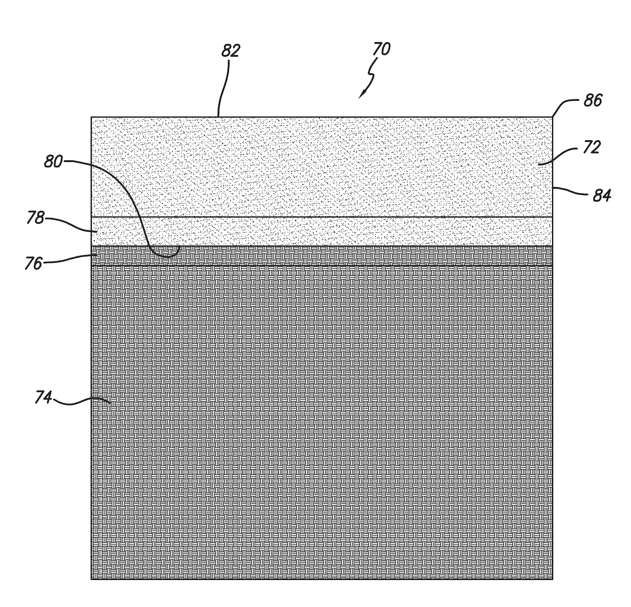
[0017]Diamond bonded constructions, prepared according to principles of the invention, are engineered having an enhanced desired degree of thermal stability along with an improved degree of attachment strength with a metallic substrate to thereby provide improved performance properties and extended service life when compared to conventional thermally stable diamond bonded constructions.

Problems solved by technology

While TSP provides desired improvements in thermal stability, a problem known to exist with TSP is that its lack of catalyst material within the body operates to preclude subsequent attachment of the TSP body to a metallic substrate by solvent catalyst infiltration.
However, the difference in thermal expansion between the TSP body and the substrate, and the poor wettability of the TSP body due to the substantial absence of the catalyst material, makes it very difficult to bond the TSP body to conventionally used substrates.
However, because of the poor wettability of the TSP body, the attachment that is formed between the TSP body and the substrate by conventional brazing techniques is one that is not as strong as the attachment bond formed between conventional PCD and a metallic substrate by infiltration, thus is one that can result in diminished service life due to delamination or the like between the TSP body and the substrate.

Method used


Image

  • Diamond Bonded Construction with Improved Braze Joint
  • Diamond Bonded Construction with Improved Braze Joint
  • Diamond Bonded Construction with Improved Braze Joint

Examples


Embodiment Construction

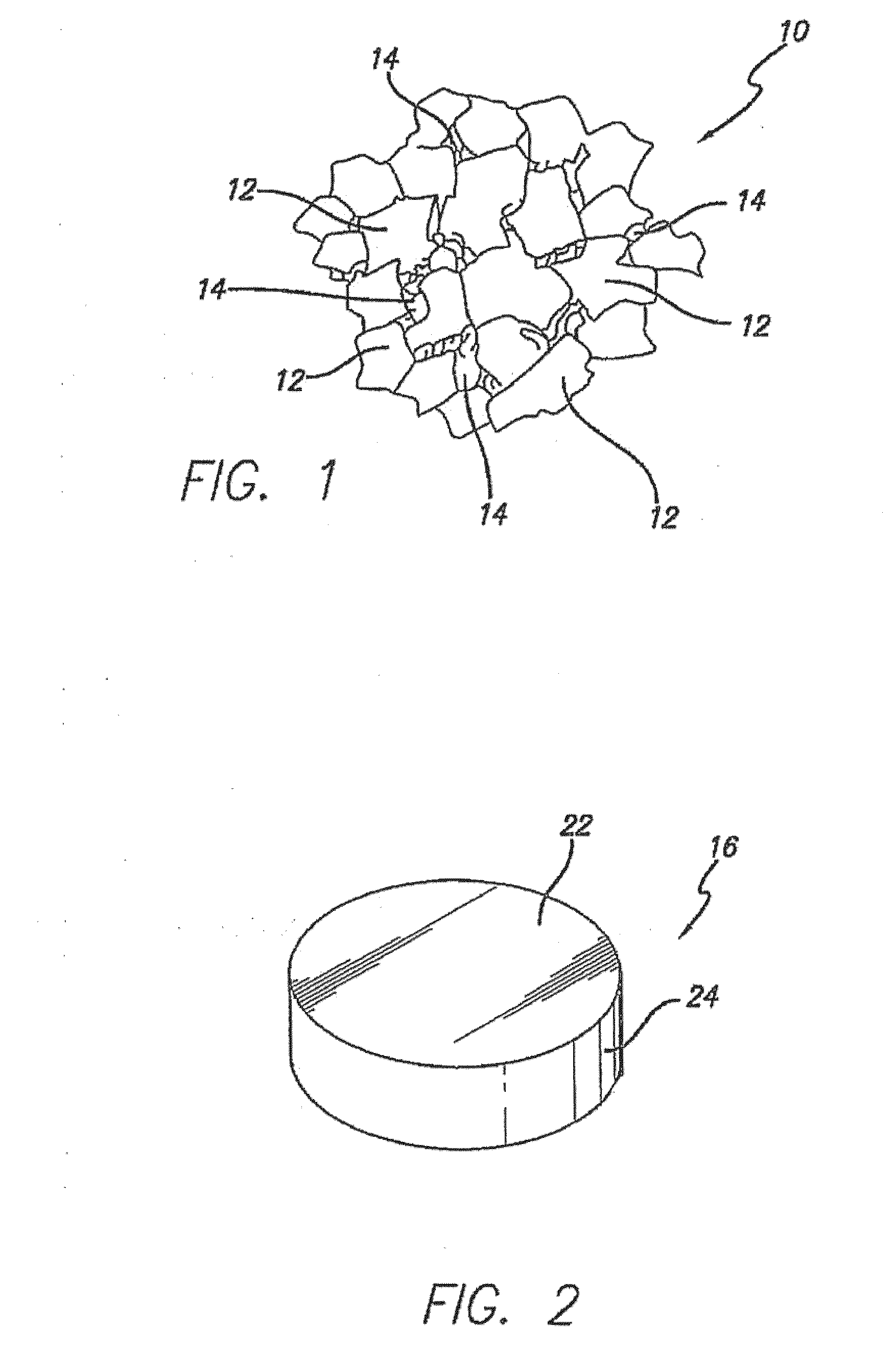
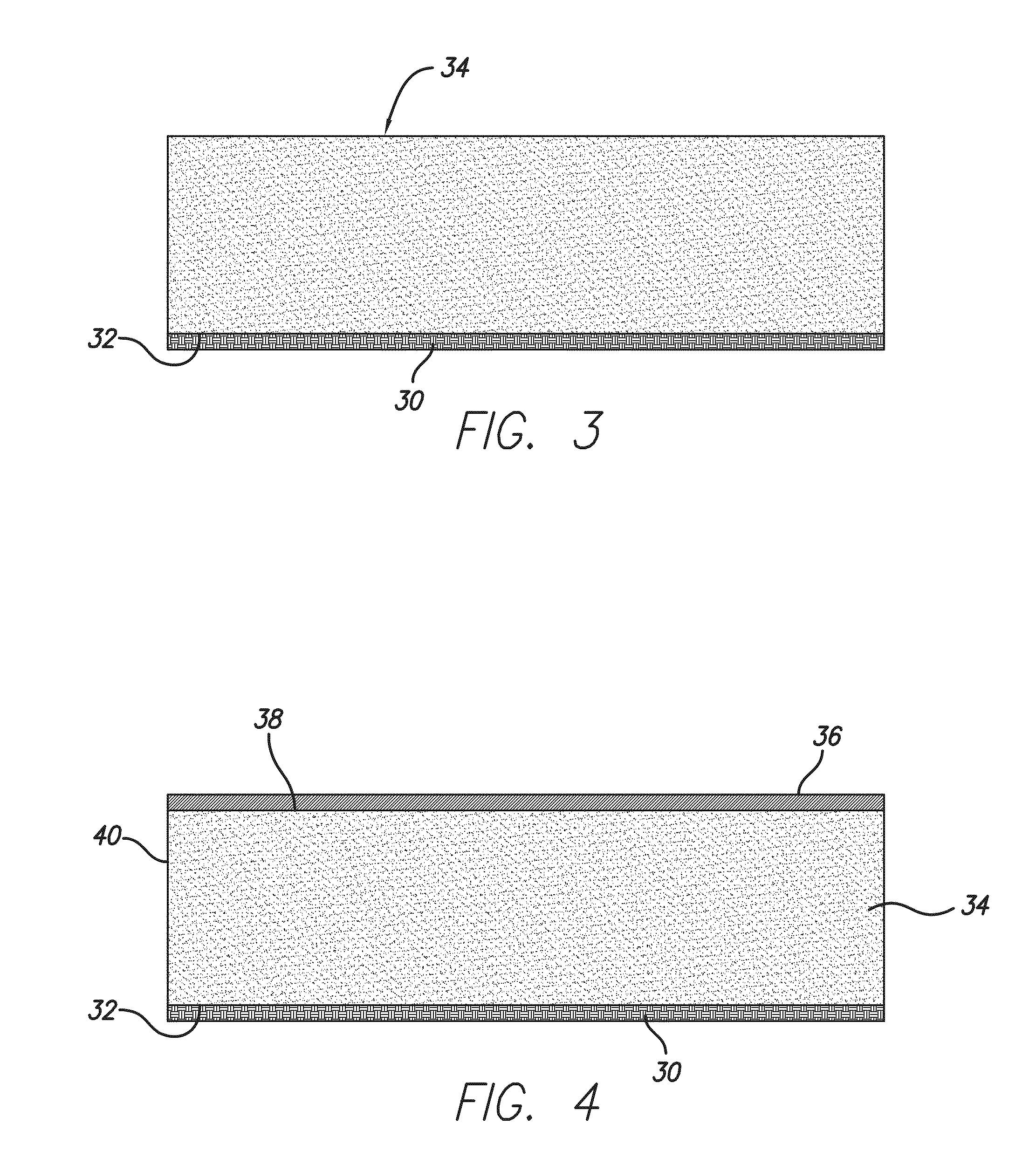
[0032]Ultra-hard and metallic constructions of this invention comprise a thermally stable polycrystalline diamond (TSP) bonded body that is substantially free of the catalyst material that was initially used to sinter the body, and that is specially engineered to accommodate attachment with a substrate or end use device by a braze joint in a manner that provides an enhanced degree of attachment strength therewith and optionally to provide an improved degree of strength and toughness along a working surface when compared to conventional TSP constructions.

[0033]As used herein, the term “ultra-hard” is understood to refer to those materials known in the art to have a grain hardness of about 4,000 HV or greater. Such ultra-hard materials can include those capable of demonstrating physical stability at temperatures above about 750° C., and for certain applications above about 1,000° C., that are formed from consolidated materials. Such ultra-hard materials can include but are not limited...


PUM

PropertyMeasurementUnit
Thicknessaaaaaaaaaa
Lengthaaaaaaaaaa
Depthaaaaaaaaaa

Abstract

Diamond bonded constructions comprise a body comprising a plurality of bonded together diamond grains with interstitial regions disposed between the grains that are substantially free of the catalyst material used to initially sinter the body. A metallic substrate is attached to the body, and a braze joint is interposed between the body and the substrate. The body is metallized to include a metallic material disposed along a substrate attachment surface in contact with the braze joint, wherein the metallic material is different from the braze joint material. The metallic material may exist within a region of the body extending fully or partially into the body, and / or may exist as a layer extending away from the substrate attachment surface. The body includes a working surface characterized by empty interstitial regions or by interstitial regions filled with an infiltrant material, wherein the infiltrant material is different from the metallizing material.

Description

FIELD OF THE INVENTION[0001]This invention generally relates to constructions comprising an ultra-hard component and a metallic component that are brazed together and, more particularly, to a thermally stable diamond bonded body that is specially engineered to facilitate attachment with a metallic substrate using a braze joint in a manner that provides improved attachment strength therebetween, thereby improving the effective service life of the construction formed therefrom when compared to conventional thermally stable diamond bonded constructions.BACKGROUND OF THE INVENTION[0002]The use of constructions comprising ultra-hard and metallic components that are joined together is well known in the art. An example of such can be found in the form of cutting elements comprising an ultra-hard component that is joined to a metallic component. In such cutting element embodiment, the wear or cutting portion is formed from the ultra-hard component and the metallic portion of the cutting ele...

Claims


Application Information

Patent Timeline
IPC IPC(8): E21B10/573E21B10/567B23K31/02B21C1/00
CPCC04B35/645C04B2237/401C04B2235/427C04B2237/083C04B2237/062B24D18/0009C04B2237/122Y10T428/12229C04B37/025E21B10/5735C04B2237/72B22F7/08C04B2237/121C04B2237/08C04B37/026C04B2237/363C04B35/52C04B2237/124C04B2235/6567E21B10/573B22F2005/001C04B2237/12C04B2237/125B23K1/0008C22C1/1036C04B2237/068C04B2237/123C04B2237/064C22C26/00B24D3/10B23K1/20E21B10/46C04B37/02
Inventor CARIVEAU, PETERVORONIN, GEORGIYBELNAP, J. DANIEL
Owner SMITH INT INC
Learn More