
Drill bits for drilling wells

a drilling well and drill bit technology, applied in the direction of drill bits, drilling accessories, earth-moving drilling and mining, etc., can solve the problems of insufficient lubrication, relatively quick wear of lubricant rods, and high cost of changing bits for new ones, so as to reduce the operation and maintenance costs of drilling installations, improve lubrication and cooling, and prolong the operation term of basic parts

Inactive Publication Date: 2010-12-02
YATSENKO YURIY +2
View PDF7 Cites 4 Cited by
  • Summary
  • Abstract
  • Description
  • Claims
  • Application Information

AI Technical Summary

Benefits of technology

[0005]Therefore, the primary aim of the present invention is to provide efficient drill bits for speedy drilling deep boreholes for mining and other industries, which bits should be provided with improved lubrication and cooling means, and also should be preferably re-assembleable to extend the operation term of their basic parts. In some preferred embodiments, the inventive bit should also allow drilling the boreholes without rotation of the bore string that significantly reduces operation and maintenance costs of drilling installations. Other aims of the invention might become apparent to a skilled artisan upon learning the present disclosure.

Problems solved by technology

In practice this lubrication is insufficient for durable exploitation of the bits that leads to their overheating and failure, and consequently to changing the bit for a new one that is very costly.
A drawback of such a device is that the lubricant rod relatively quickly wears out, and the bit continues rotation essentially without lubrication.
This involves either failure, or destruction of the bit, or significant expenses for frequent replacements of the lubricant rod.

Method used


Image

  • Drill bits for drilling wells
  • Drill bits for drilling wells
  • Drill bits for drilling wells

Examples


Embodiment Construction

[0018]While the invention may be susceptible to embodiment in different forms, there is shown in the drawing, and will be described in detail herein, a specific embodiment of the present invention, with the understanding that the present disclosure is to be considered an exemplification of the principles of the invention, and is not intended to limit the invention to that as illustrated and described herein.

First Version of Inventive Drill Bit

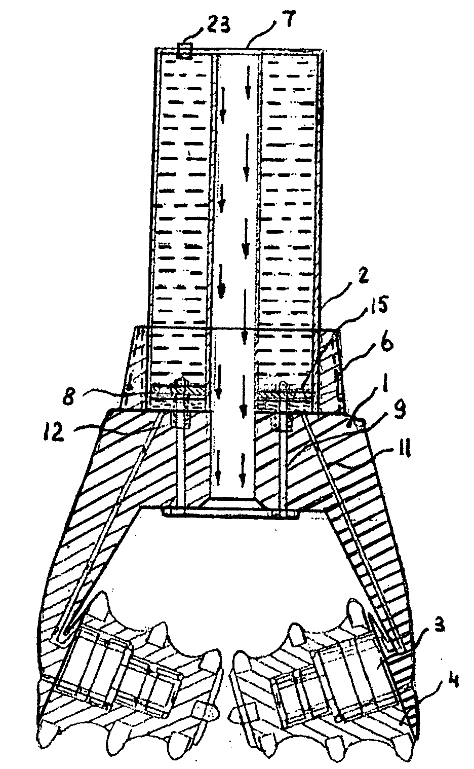
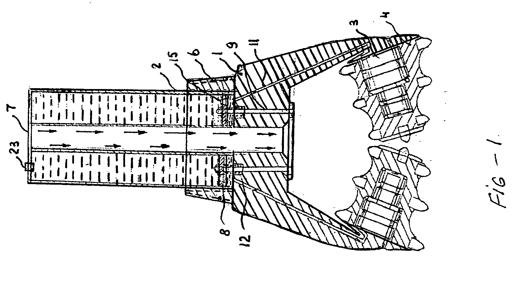
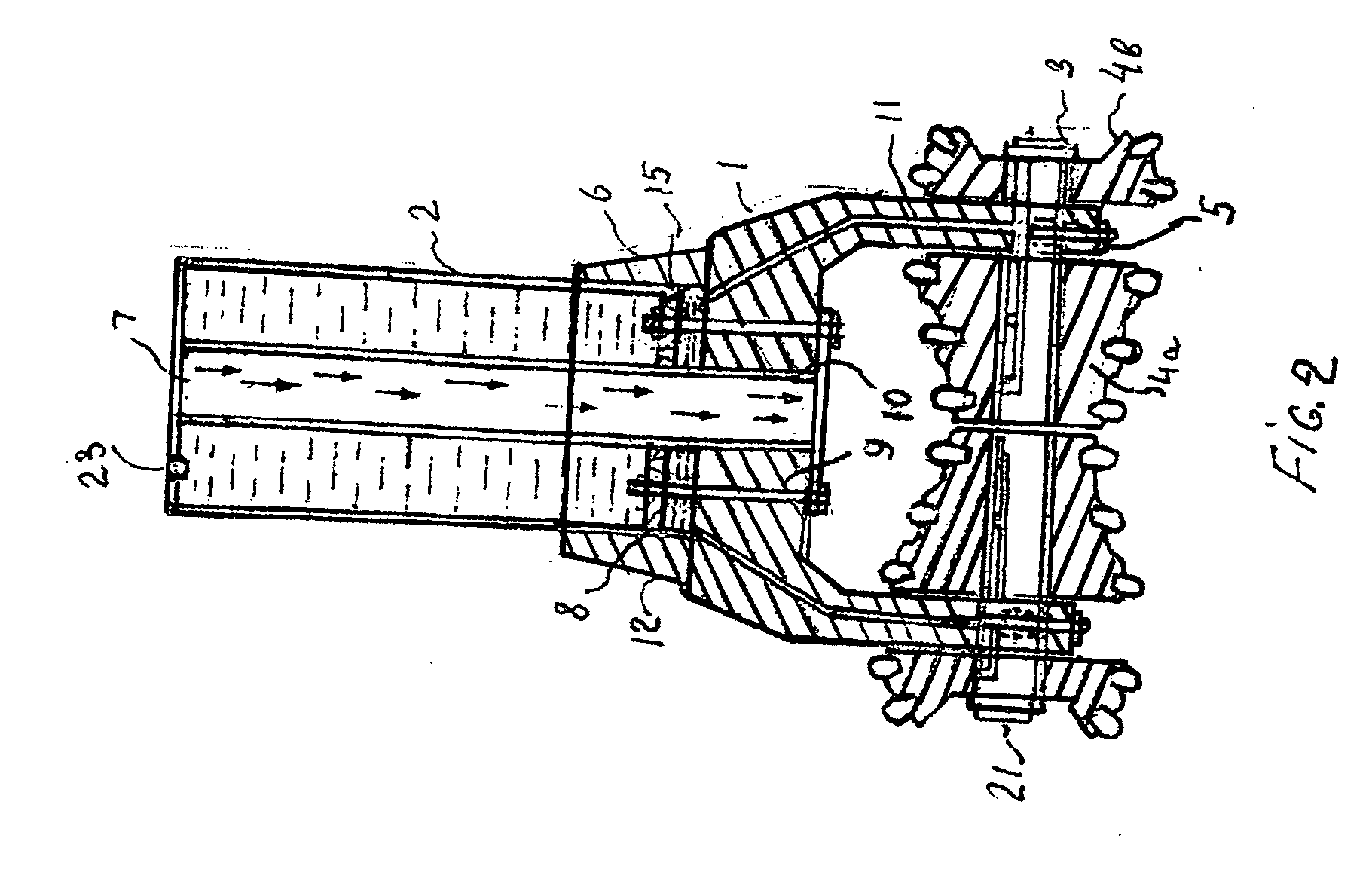
[0019]In a preferred embodiment illustrated on FIG. 1, an inventive drill bit (101) comprises: three lug members (1) arranged at a 120 degree angle to each other and joined by an upper support member (6) of an annular shape, preferably having an outer screw threading substantially for connection to the lower pipe of the bore string (not shown) or for connection to an intermediate member therebetween, e.g. a turbo-gear (100) shown on FIG. 4 (according to the aforementioned U.S. patent application Ser. No. 12 / 291,239). Each lug member 1 includes ...


PUM


Abstract

A device including a drill bit is disclosed. The bit preferably comprises lug members, joined by a support member, each lug member includes a through hole, bearings rotatably mounted on the lug members which bearings support cutter members, a sleeve with lubricant mounted upon the support member, a central channel within the sleeve whose lower end can be closed or opened with a reciprocating valve-plate, an annular piston snug-fitting between the sidewalls of sleeve and central channel, which piston has a discharge valve outletting the lubricant through the piston, a spring disposed in the sleeve, rods mounted in the sleeve and inserted through the holes, lubrication channels arranged in the lug members and communicating the lower portion of sleeve with the bearings for lubrication thereof. The rods are coupled to the piston and the valve-plate. Embodiments include shafts supporting the bearings. Some shafts are hollow and have a coolant system.

Description

TECHNICAL FIELD[0001]The invention relates to bore or drilling devices utilized in the oil and gas extracting industries, in the water supply industry, etc., specifically to downhole drill bits deployed for the fast drilling of deep wells.BACKGROUND OF THE INVENTION[0002]There are known many different tools and devices for drilling oil, gas, and water wells. A traditional device is usually composed of a bore string consisting of a plurality of tubular pipes driven by a power unit typically located on the surface. The power unit provides rotation of the pipes in turn revolving a drill bit that actually performs the drilling. Typically, lubrication of such drill bits is provided during the assembling process at manufacturer's facilities. In practice this lubrication is insufficient for durable exploitation of the bits that leads to their overheating and failure, and consequently to changing the bit for a new one that is very costly.[0003]There have been proposed some devices to improv...

Claims


Application Information

Patent Timeline
IPC IPC(8): E21B10/24
CPCE21B10/24
Inventor YATSENKO, YURIYAVRAMCHUK, BORISZMITKOVICH, SIARHEI
Owner YATSENKO YURIY
Learn More