Indwelling device
a technology of indwelling devices and dilators, which is applied in the direction of wound drains, dilators, catheters, etc., can solve the problems of further infection around the device and undesirable blood clot formation, and achieve the effect of preventing the build-up of biofilm
- Summary
- Abstract
- Description
- Claims
- Application Information
AI Technical Summary
Benefits of technology
Problems solved by technology
Method used
Image
Examples
first embodiment
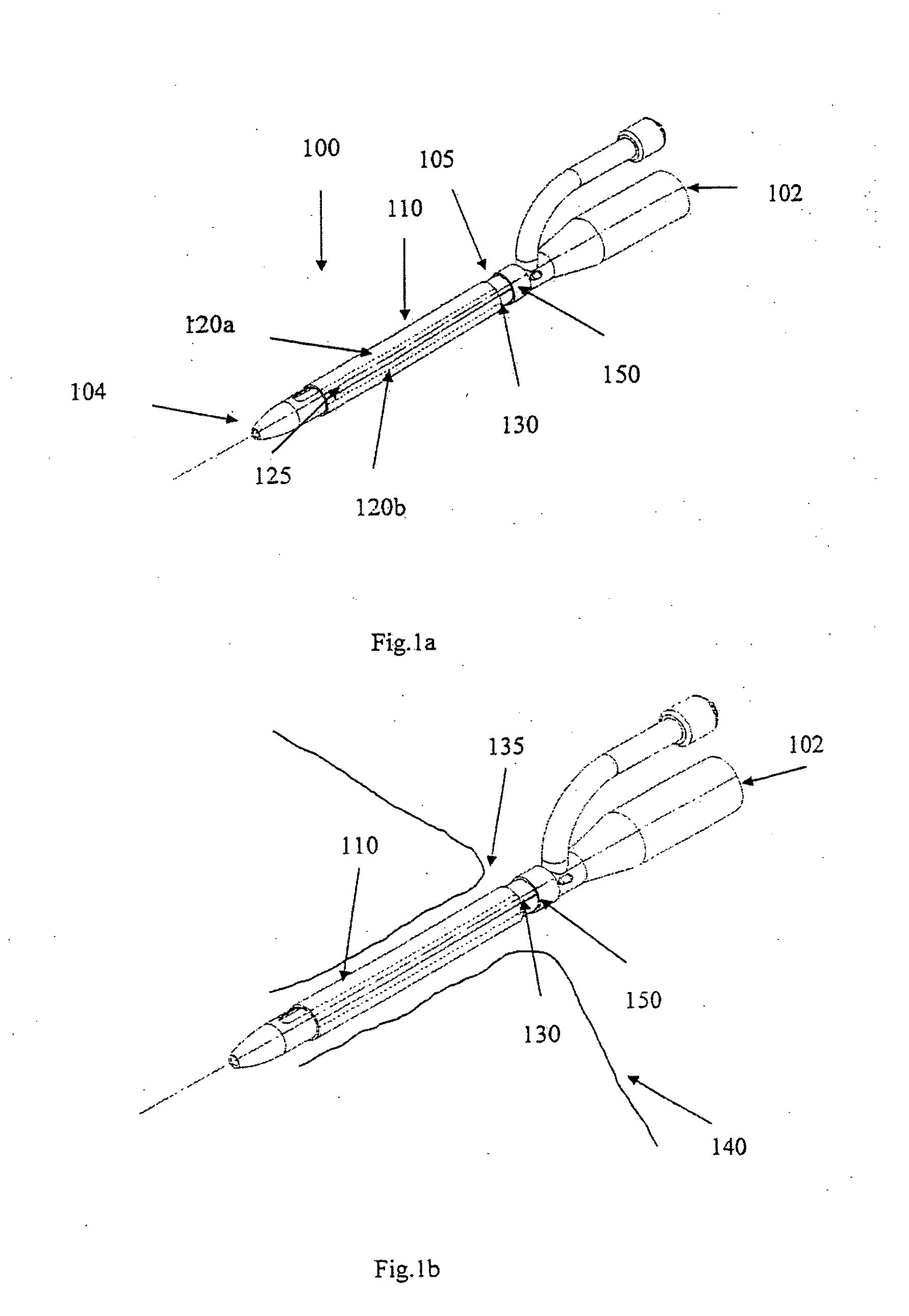
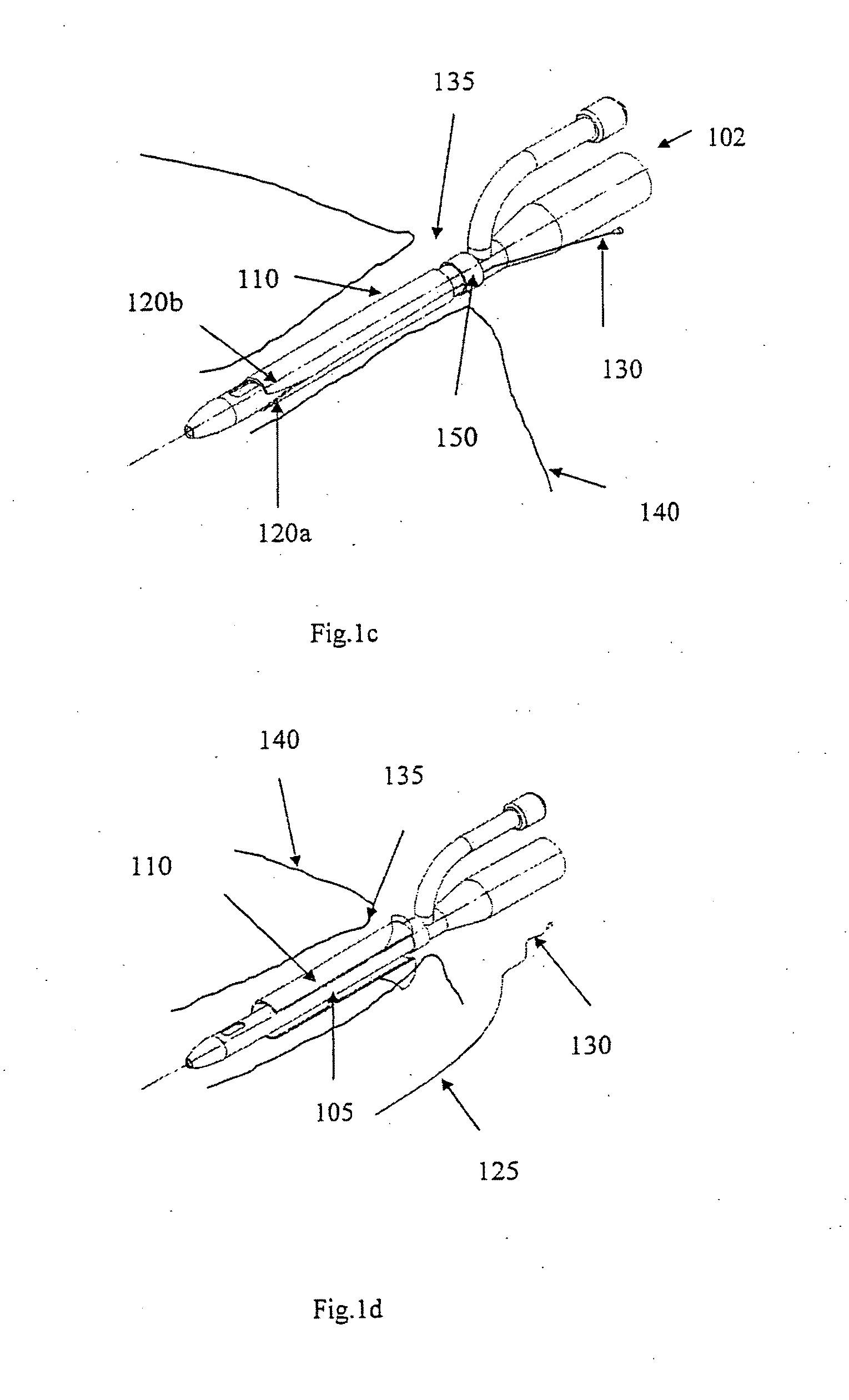
[0057]FIG. 1a shows an indwelling device 100 in accordance with a first embodiment of the invention. The device 100 has a proximal end 102, a distal end 104, and a cylindrical shaft 105 that may be solid or hollow. The shaft 105 is contained in an outer cover 110 having the general shape of a thin cylindrical shell. The outer cover 110 is formed from a biocompatible, elastic material, such as latex, that was stretched over the shaft 105, and allowed to contract on the shaft 105. The outer cover 110 is reversibly attached to the shaft 105 by circumferential elastic forces in the outer cover 110 that are exerted on the shaft 105. This prevents slipping of the outer cover 110 over the shaft 105 during insertion of the device 100 into the body, and maintains the outer cover 110 on the shaft 105 after insertion.
[0058]The outer cover 110 is formed from two materials. The first material is used to form the cover except in a narrow strip 125 that is formed from a second material. The two ma...
second embodiment
[0071]FIG. 2a shows an indwelling device 200 in accordance with another embodiment of the invention. The device 200 has a proximal end 202, a distal end 204, and a cylindrical shaft 205 that may be solid or hollow. The shaft 205 is contained in an outer cover 210 having the general shape of a thin cylindrical shell. The outer cover 210 is formed from a biocompatible, elastic material, such as latex, that was stretched over the shaft 205, and allowed to contract on the shaft 205. The outer cover 210 is reversibly attached to the shaft 205 by circumferential elastic forces in the outer cover 210 that are exerted on the shaft 205. This prevents slipping of the outer cover 210 over the shaft 205 during insertion of the device 200 into the body, and maintains the outer cover 210 on the shaft 205 after insertion.
[0072]As shown in the insert FIG. 2a-I of FIG. 2a, the shaft has a longitudinal groove 215 that forms a track for a blade 220. The blade 220 is slidable along the groove 215. Duri...
third embodiment
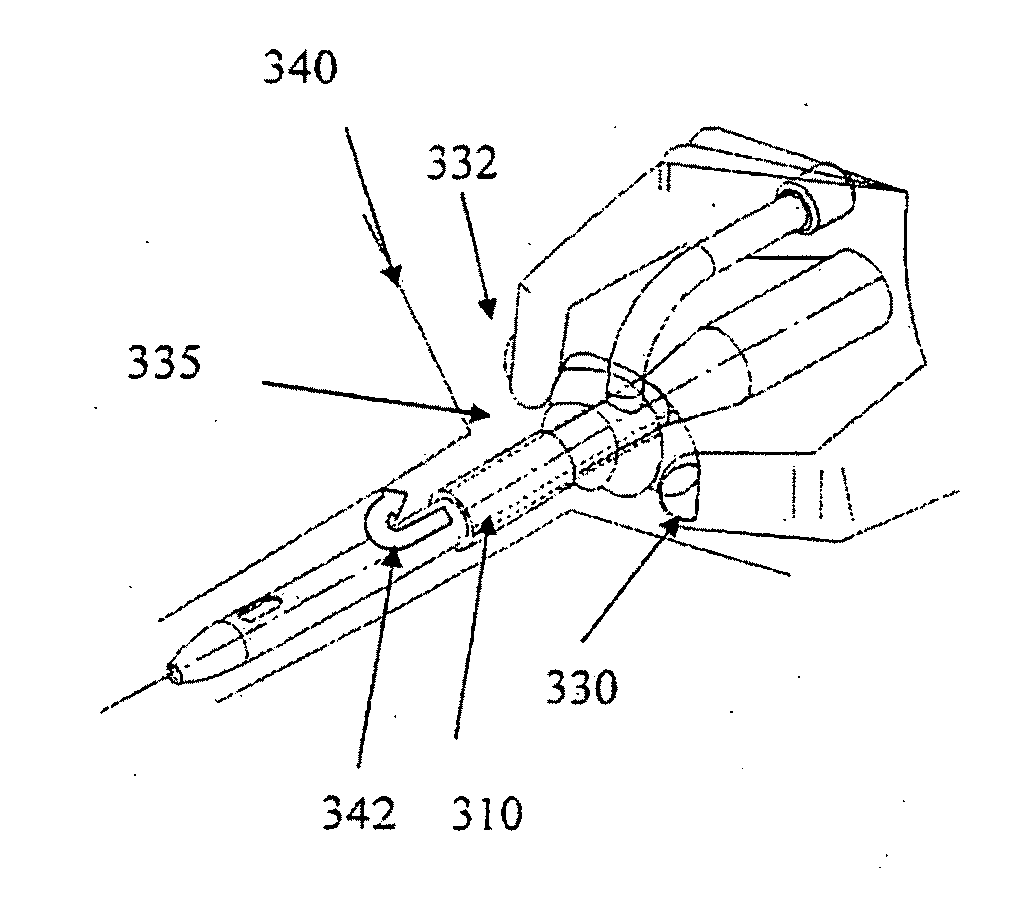
[0075]FIG. 3a shows a device 300 in accordance with another embodiment of the invention. The device 300 has a proximal end 302, a distal end 304, and a cylindrical shaft 305. The shaft 305 is contained in an outer cover 310 having the general shape of a thin cylindrical shell. The outer cover 310 is formed from a biocompatible, elastic material, such as latex. The outer cover 310 was formed from an inner cylindrical shell 322 and an outer cylindrical shell 324. The inner and outer shells 322 and 324 are welded together at a first circular seam 326 at its distal end and a second circular seam 327 at its proximal end. The outer cover 310 was stretched over the shaft 305, and allowed to constrict on the shaft 305. The outer cover 310 is reversibly attached to the shaft 305 by circumferential elastic forces in the outer cover 310 that are exerted on the shaft 305. This prevents movement of the outer cover 310 relative to the shaft 305 during insertion of the device 300 and maintains the...
PUM
 Abstract
Description
Claims
Application Information
 - R&D
- Intellectual Property
- Life Sciences
- Materials
- Tech Scout
- Unparalleled Data Quality
- Higher Quality Content
- 60% Fewer Hallucinations
Browse by: Latest US Patents, China's latest patents, Technical Efficacy Thesaurus, Application Domain, Technology Topic, Popular Technical Reports.
© 2025 PatSnap. All rights reserved.Legal|Privacy policy|Modern Slavery Act Transparency Statement|Sitemap|About US| Contact US: help@patsnap.com


