Transceiver
a technology of transceivers and receivers, applied in the field of transceivers, can solve the problems of shortening the transmittable range, and achieve the effects of reducing power consumption, preventing interference with other systems, and increasing transmission capacity
- Summary
- Abstract
- Description
- Claims
- Application Information
AI Technical Summary
Benefits of technology
Problems solved by technology
Method used
Image


Examples
second embodiment
[0067]The following describes the operation procedure for switching the wireless communication from the 5 GHz band wireless communication to the millimeter wave band wireless communication.
[0068]FIG. 4 is a diagram showing this operation and, in this figure, the reception quality value of the 5 GHz band wireless communication and the reception quality value of the millimeter wave band wireless communication are shown side by side to indicate how they change over time. FIG. 5 is a flowchart showing an example of operation for switching the wireless communication from the 5 GHz band wireless communication to the millimeter wave band wireless communication.
[0069]Referring to the flowchart in FIG. 5, the reception control unit 24 regularly acquires the reception quality value of the 5 GHz band wireless communication from the 5 GHz band reception unit 23 while the signal is transmitted and received via the 5 GHz band wireless communication (step S501). To reduce the power consumption, it...
third embodiment
[0076]In the example of operation described in the second embodiment, the reception quality value of the millimeter wave band wireless communication is checked when the reception quality value of the 5 GHz band wireless communication is varied. The following describes another example of operation.
[0077]FIG. 6 is a block diagram showing the configuration of a wireless transceiver in a third embodiment of the present invention. As shown in FIG. 6, the reception device 20 described above, a sensor sensing unit 31, and a display driving detection unit 32 are fixed internally or externally in a display 30 on which an HD stream signal, received by the reception device 20, is displayed. The sensor sensing unit 31, which includes a sensor capable of sensing the movement of an object such as a gravity sensor or an accelerometer, can detect that the display 30 is moved, for example, by human hands. The display driving detection unit 32 can detect that the direction of the display is changed, ...
fourth embodiment
[0082]Although, in the description of the first embodiment to the third embodiment, various control information is transmitted between the transmission control unit 14 and the reception control unit 24 via the wireless communication at a predetermined frequency (for example, 2.4 GHz band that does not require a wireless station license or the frequency of 38 kHz used by an infrared remote control), control information may be transmitted also via the millimeter wave band wireless communication or the 5 GHz band wireless communication. The following describes how to implement this transmission.
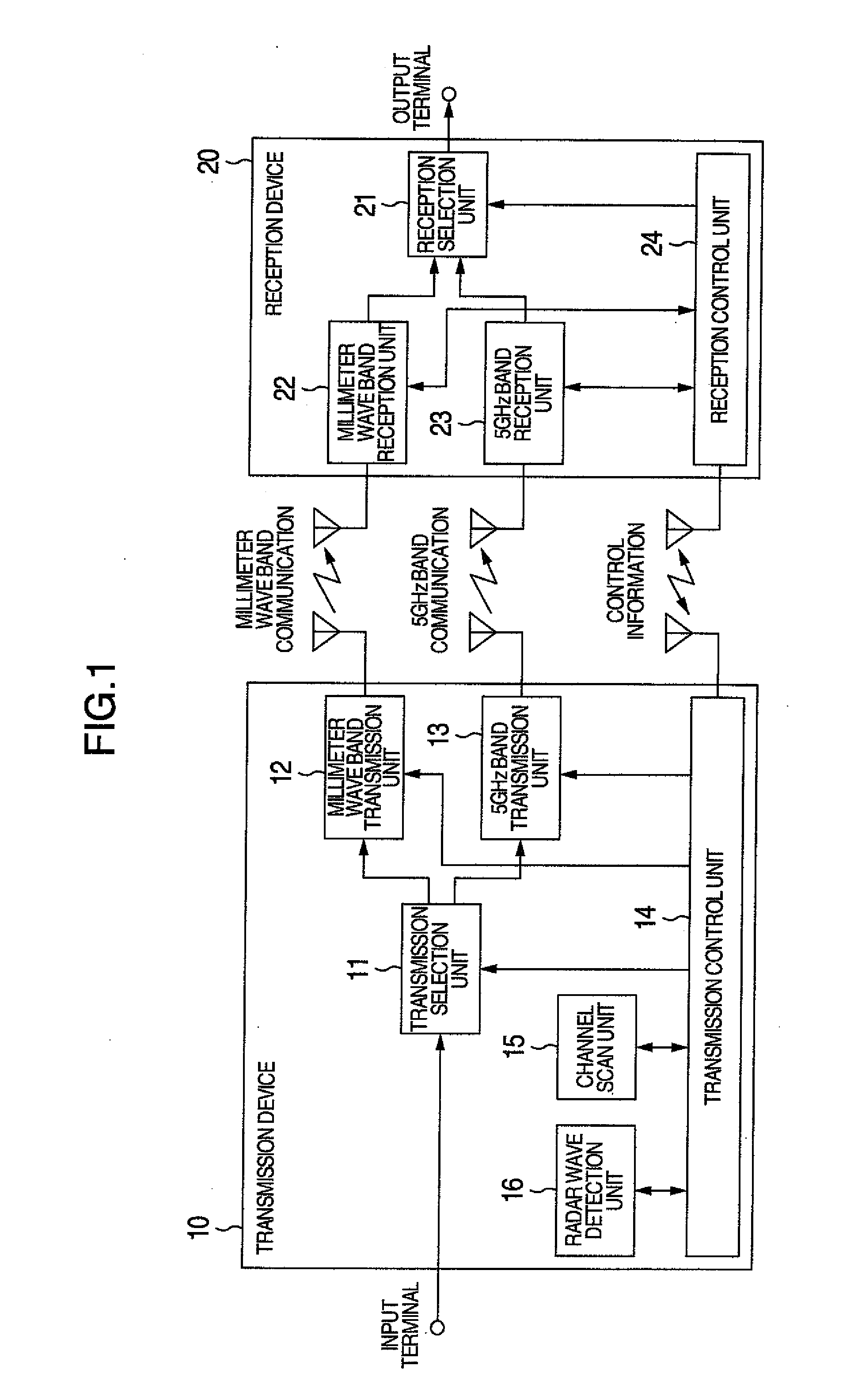
[0083]The millimeter wave band transmission unit 12 and the 5 GHz band transmission unit 13, shown in FIG. 1, each have the function not only to transmit, but also to receive, signals via the millimeter wave band wireless communication and the 5 GHz band wireless communication. Similarly, the millimeter wave band reception unit 22 and the 5 GHz band reception unit 23 each have the function not o...
PUM
 Abstract
Description
Claims
Application Information
 - R&D
- Intellectual Property
- Life Sciences
- Materials
- Tech Scout
- Unparalleled Data Quality
- Higher Quality Content
- 60% Fewer Hallucinations
Browse by: Latest US Patents, China's latest patents, Technical Efficacy Thesaurus, Application Domain, Technology Topic, Popular Technical Reports.
© 2025 PatSnap. All rights reserved.Legal|Privacy policy|Modern Slavery Act Transparency Statement|Sitemap|About US| Contact US: help@patsnap.com