
Process for manufacturing an optical fiber and an optical fiber so obtained

a manufacturing process and optical fiber technology, applied in the field of optical fibers, can solve the problems of difficult control of the diameter of the layers, cumbersome manufacturing of colored optical fibers with elastic modulus values radially increasing departing from the optical fiber longitudinal axis, etc., and achieve the effect of modulating the elastic modulus and increasing the curing degr

Active Publication Date: 2010-11-25
PRYSMIAN SPA
View PDF13 Cites 13 Cited by
  • Summary
  • Abstract
  • Description
  • Claims
  • Application Information

AI Technical Summary

Benefits of technology

[0027]coating layers with elastic modulus values radially increasing departing from the optical fiber longitudinal axis, so as to improve characteristics of microbending resistance;
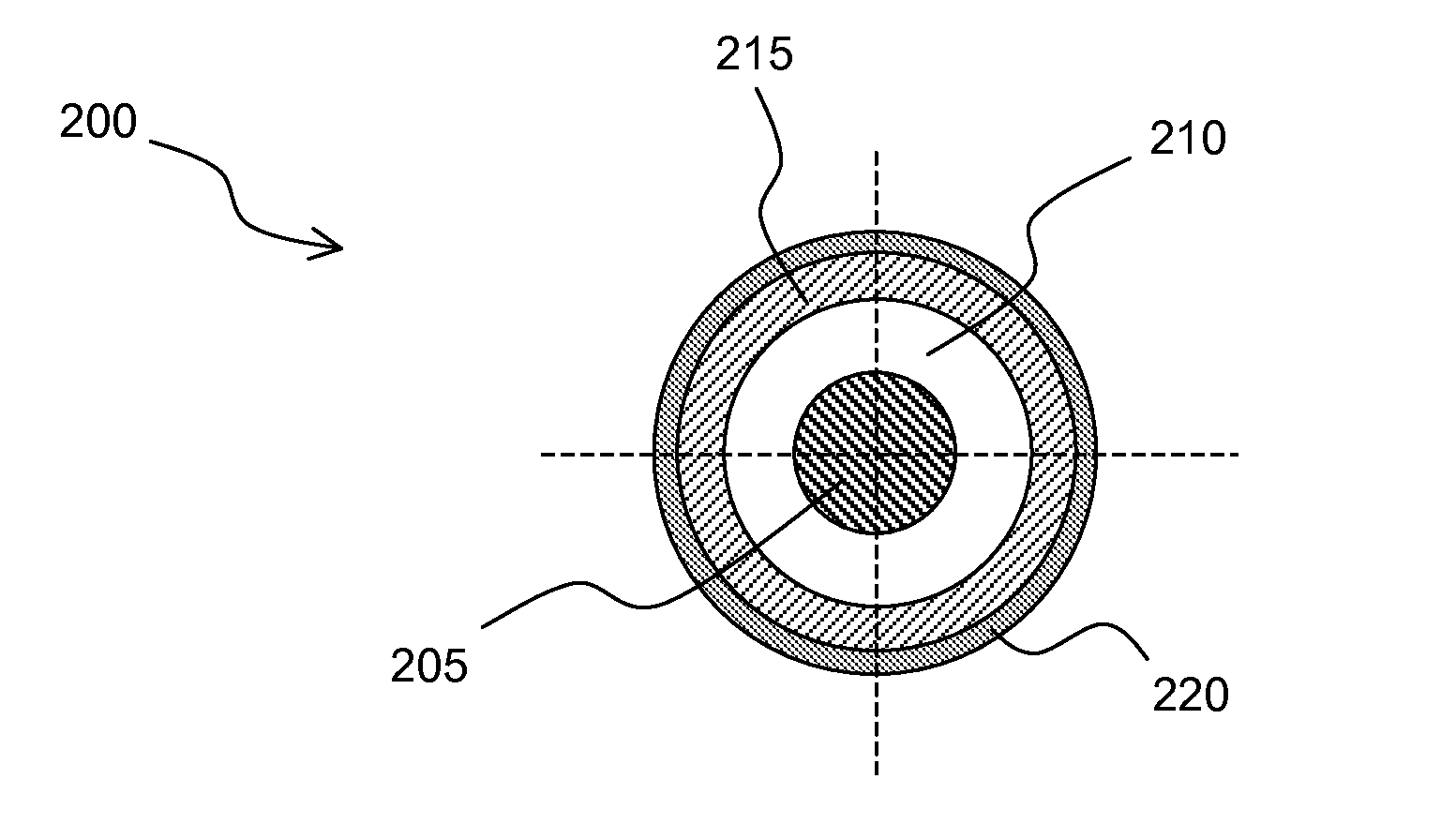
[0085]The optical fiber manufactured according to the present invention is a three coating layered-optical fiber. This optical fiber exhibits good fiber performances in terms of break-out, handling and aging in water, and shows microbending performances at least equivalent to that of the prior-art. Without being bound to a particular theory, it is believed that said performances could be due to the fact that the layer of colored coating material acts as a shield against the curing radiation. Therefore, the layer of second coating material experiences less radiation power than in the case of a two layered coating. The layer of second coating material, even if formed of the same material of the colored coating material, has a lower modulus after curing.

Problems solved by technology

The Applicant has observed that the manufacturing of a colored optical fiber with coating layers with elastic modulus values radially increasing departing from the optical fiber longitudinal axis can be cumbersome.
Such a process is wholly wet-on-wet, as will be explained hereinbelow, and makes it difficult to control the diameters of the layers, especially when the layers are three.

Method used


Image

  • Process for manufacturing an optical fiber and an optical fiber so obtained
  • Process for manufacturing an optical fiber and an optical fiber so obtained
  • Process for manufacturing an optical fiber and an optical fiber so obtained

Examples


Embodiment Construction

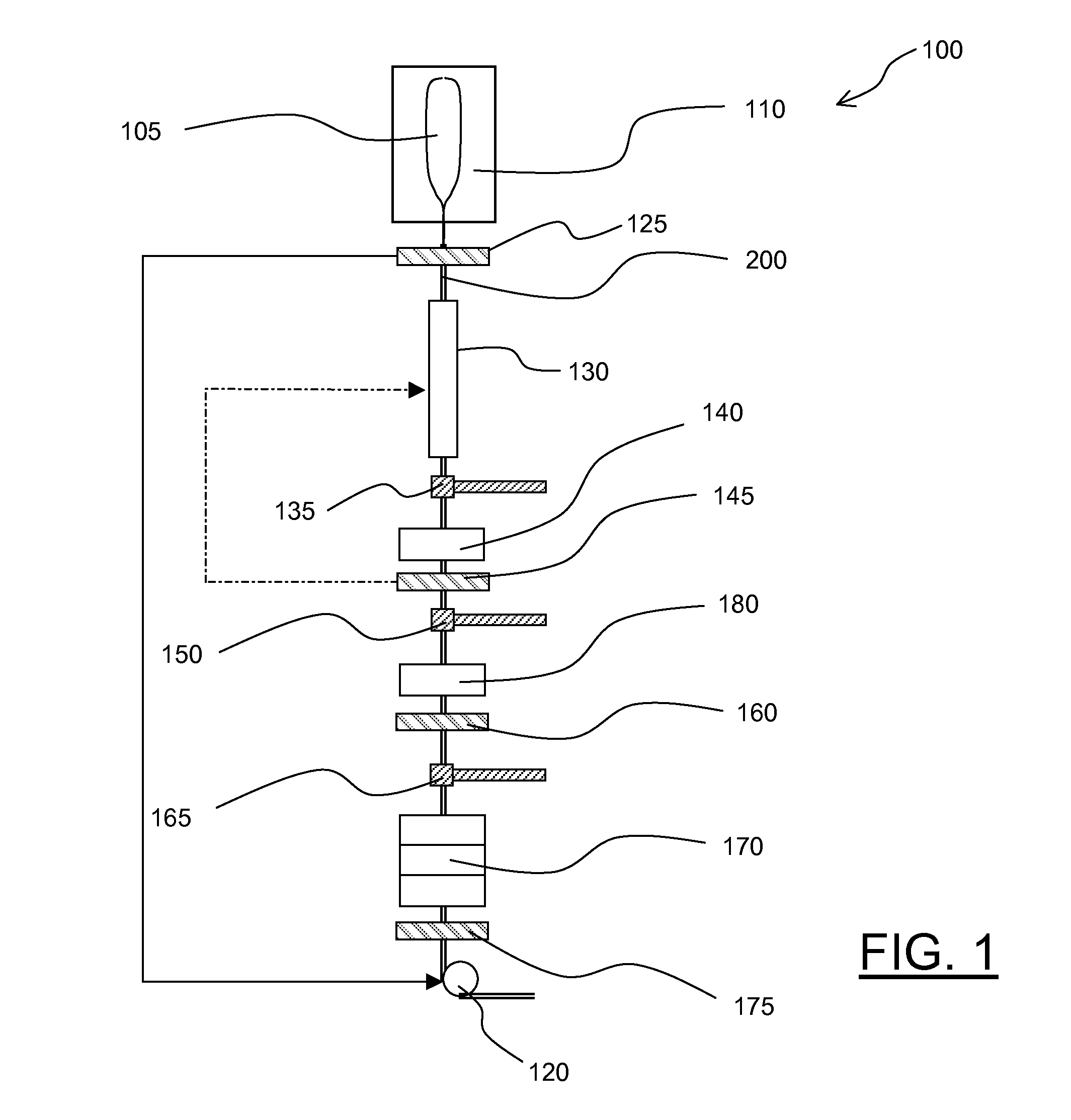
[0090]Making reference to the drawings, in FIG. 1 an apparatus 100 according to an embodiment of the present invention is schematically depicted, for the manufacturing of a three coating-layered optical fiber 200 by a method according to an embodiment of the present invention.

[0091]In particular, the apparatus 100 of FIG. 1 is a vertical draw apparatus, to be mounted in an optical fiber drawing tower, suitable for a wet-on-dry application of all the three layers of the three layered optical fiber. It is pointed out that different apparatus layouts, for example suitable for a wet-on-wet or mixed wet-on-wet / wet-on-dry application of the three layers are also possible. The drawing tower and resin applicators of the wet-on-wet or wet-on-dry type are known per se and will not be described in detail.

[0092]A glass preform 105 is drawn in a furnace 110 to obtain the optical waveguide of the fiber 200. The fiber 200 is taken down by a tractor 120. During the drawing, the diameter of the fibe...


PUM

PropertyMeasurementUnit
Fractionaaaaaaaaaa
Fractionaaaaaaaaaa
Fractionaaaaaaaaaa

Abstract

A process for manufacturing an optical fiber includes: drawing an optical waveguide from a glass preform; applying a layer of a first coating material on the optical waveguide; curing the first coating layer material to obtain a first coating layer; applying a layer of a second coating material onto the first coating layer; applying a layer of colored coating material onto the second coating layer; curing the second coating material and the colored coating material in a single step to obtain a second coating layer superposed on the first coating layer and a colored coating layer superposed on the second coating material layer, the obtained second coating layer having an elastic modulus higher than that of the first coating layer and lower than that of the colored coating layer. An optical fiber and an apparatus for producing it are also provided.

Description

BACKGROUND OF THE INVENTION[0001]1. Field of the Invention[0002]The present invention generally relates to the field of optical fibers and of the manufacturing thereof.[0003]2. Description of the Related Art[0004]Optical fibers, particularly glass fibers, are manufactured starting from a previously made glass body, usually called “preform”, by a process known in the art as “drawing”. A glass preform is placed at the top of a fiber drawing tower, where it is heated up in a furnace to a temperature sufficiently high to cause the softening of a bottom portion of the preform. The softened preform material is drawn by a tractor, to form an optical fiber glass core.[0005]The glass core is surrounded by a layer, generally of glass, having a refractive index lower than that of the core, said layer being called cladding. In the following, the glass core surrounded by the cladding could be referred to as “optical waveguide”.[0006]Over the cladding, at least one, more often two superposed UV r...

Claims


Application Information

Patent Timeline
IPC IPC(8): G02B6/44C03C25/12B05C11/00G02B6/00
CPCG02B6/02395C03C25/12
Inventor SCHIAFFO, ANTONIOCOCCHINI, FRANCOSCAFURO, NICOLAGALASSO, GIUSEPPE
Owner PRYSMIAN SPA
Learn More