Electromechanical vibration converter for tactile acoustic apparatus

a technology of tactile acoustic apparatus and electromechanical vibration converter, which is applied in the direction of diaphragm damping, transducer details, electrical transducers, etc., can solve the problems of inability to meet the needs the structure of electromechanical vibration converters is considerably different from the structure of dynamic speakers, and few engineers are engaged in such electromechanical vibration converters. achieve the effect of convenient production

Inactive Publication Date: 2010-11-25
AISHIN
View PDF1 Cites 14 Cited by
  • Summary
  • Abstract
  • Description
  • Claims
  • Application Information

AI Technical Summary

Benefits of technology

[0033]This invention has been made in view of the above drawbacks. It is, therefore, an object of this invention to provide an electromec

Problems solved by technology

Nevertheless, the structure of an electromechanical vibration converter is considerably different from a dynamic speaker because of differences in intended use.
On the other hand, it has not been long since an electromechanical vibration converter for a tactile acoustic apparatus was developed, and very few engineers are engaged in such an electromechanical vibration converter.
The structure of the electromechanical vibration converter is still being developed, and its standard basic structure has not yet been completed.
However, an electromechanical vibration converter is different in structure from a cone speaker.
Engineers of speakers, which have a long history and a standard basic structure with a high level of perfection, are likely to reject products other than speakers.
Furthermore, a low level of perfection in structure of electromechanical vibration converters for a tactile acoustic apparatus is likely to increase their tendency of rejection.
The difference in type of products and the low level of perfection are f

Method used


Image

  • Electromechanical vibration converter for tactile acoustic  apparatus
  • Electromechanical vibration converter for tactile acoustic  apparatus
  • Electromechanical vibration converter for tactile acoustic  apparatus

Examples


Embodiment Construction

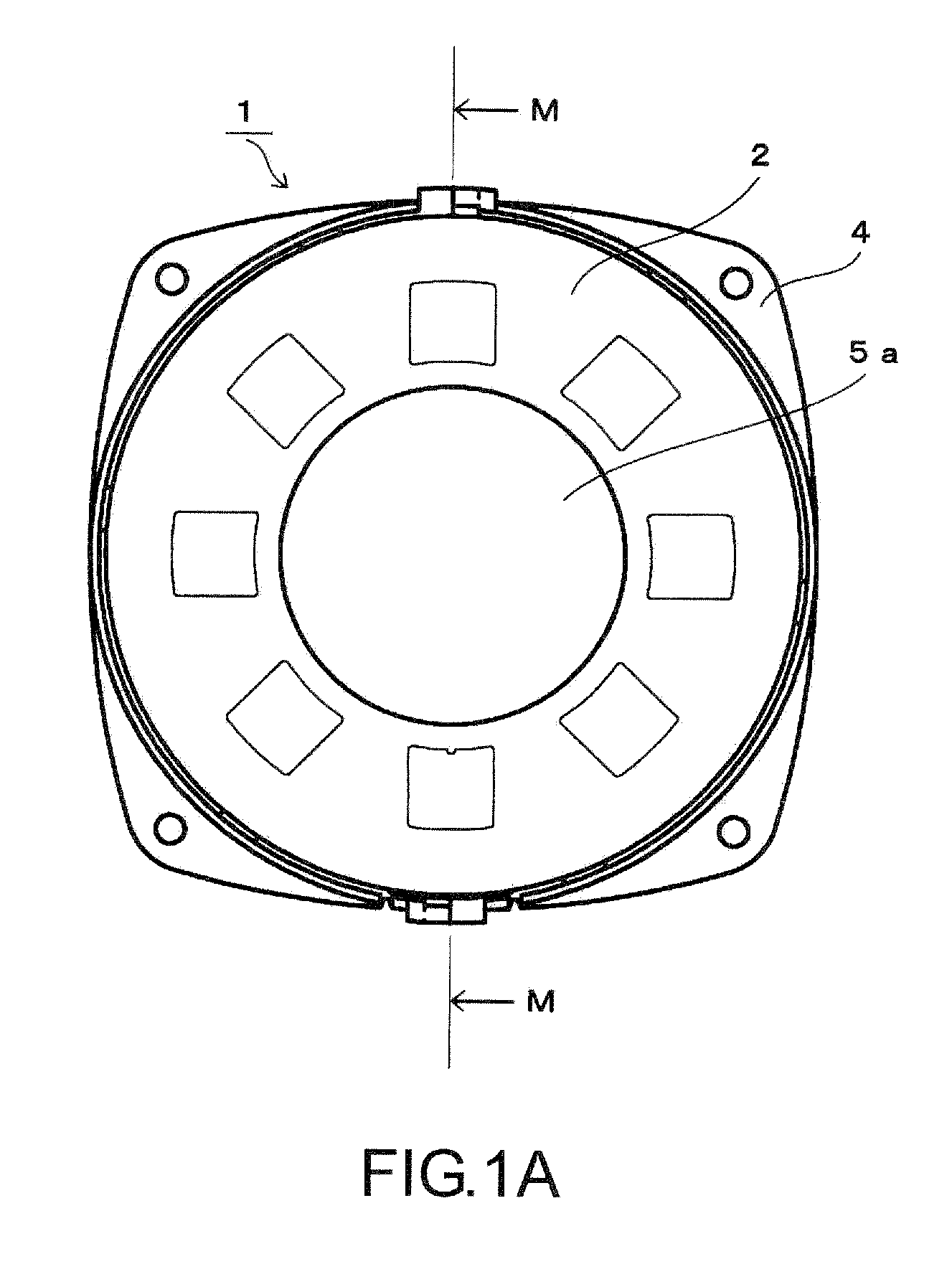
[0067]Embodiments of the invention will be described with reference to FIGS. 1A to 13F.

[0068]Components or parts corresponding to or equivalent to those in the conventional electromechanical vibration converter are denoted by the same reference numerals as in FIGS. 14 to 17.

[0069]An electromechanical vibration converter 1 includes a case, which includes an upper frame (coil holder assembly) 2 and a lower frame (case assembly) 4 and a magnetic circuit unit (magnetic circuit assembly) 3 housed in the case. The magnetic circuit unit 3 holds a magnetic circuit formed by a magnet 18 and a yoke portion 9.

[0070]The upper frame 2 is in the form of a dish. The upper frame 2 has a circular opening 5 defined at a central portion thereof. In a finished product, the opening 5 is covered with a face plate 5a.

[0071]The lower frame 4 is in the form of a dish having a two-stage structure. The lower stage has a smaller diameter and receives about a half of the magnetic circuit unit 3 other than a da...


PUM


Abstract

A damper 8 supports a yoke portion 16, 17 holding a magnet 18 therein. The damper 8 includes an annular yoke retainer portion 8a holding the yoke portion, a plurality of support portions 8b projecting radially outward from the yoke retainer portion 8a, a plurality of suspension spring portions 8c extending from each of the plurality of support portions 8b to an adjacent support portion along a periphery of the yoke retainer portion 8a, and a plurality of T-shaped projections 8T provided on an end of each of the plurality of suspension spring portions 8c. The plurality of T-shaped projections 8T are respectively fitted in notches K in a case so that the yoke portion 16, 17 is movable relative to the case. Because the damper 8 can be fixed to the case without any screws, the electromechanical vibration converter can readily be assembled and produced in a speaker manufacturing line.

Description

BACKGROUND OF THE INVENTION[0001]This invention relates to a structure of an electromechanical vibration converter used to generate vibrotactile effects from low-frequency electric signals.[0002]For example, in a simulation or a virtual reality, haptic senses produced by sound pressures vibrating a human body and haptic senses produced by vibration propagated on a floor or on the earth are important to improve the realism. Such vibration is referred to as vibrotactile effect. The realistic presence can be reproduced by vibrotactile effects relating to actual sounds involving vibrations or impulses, such as an explosion sound or an engine sound. Vibrotactile effects are used not only for an audio purpose to emphasize low-frequency sounds, but also for sound effects in a simulation or a virtual reality. Furthermore, vibrotactile effects are advantageously effective in various applications including musicotherapy using relaxation resulting from the vibrotactile effects, promotion of fe...

Claims


Application Information

Patent Timeline
IPC IPC(8): H04R11/02
CPCH04R7/26
Inventor KOMATSU, AKIRA
Owner AISHIN
Why Eureka
Try Eureka