Disc filtration device
- Summary
- Abstract
- Description
- Claims
- Application Information
AI Technical Summary
Benefits of technology
Problems solved by technology
Method used
Image
Examples
Embodiment Construction
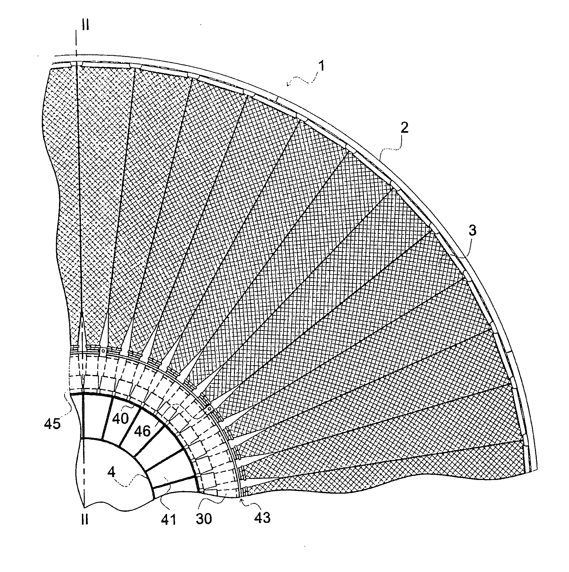
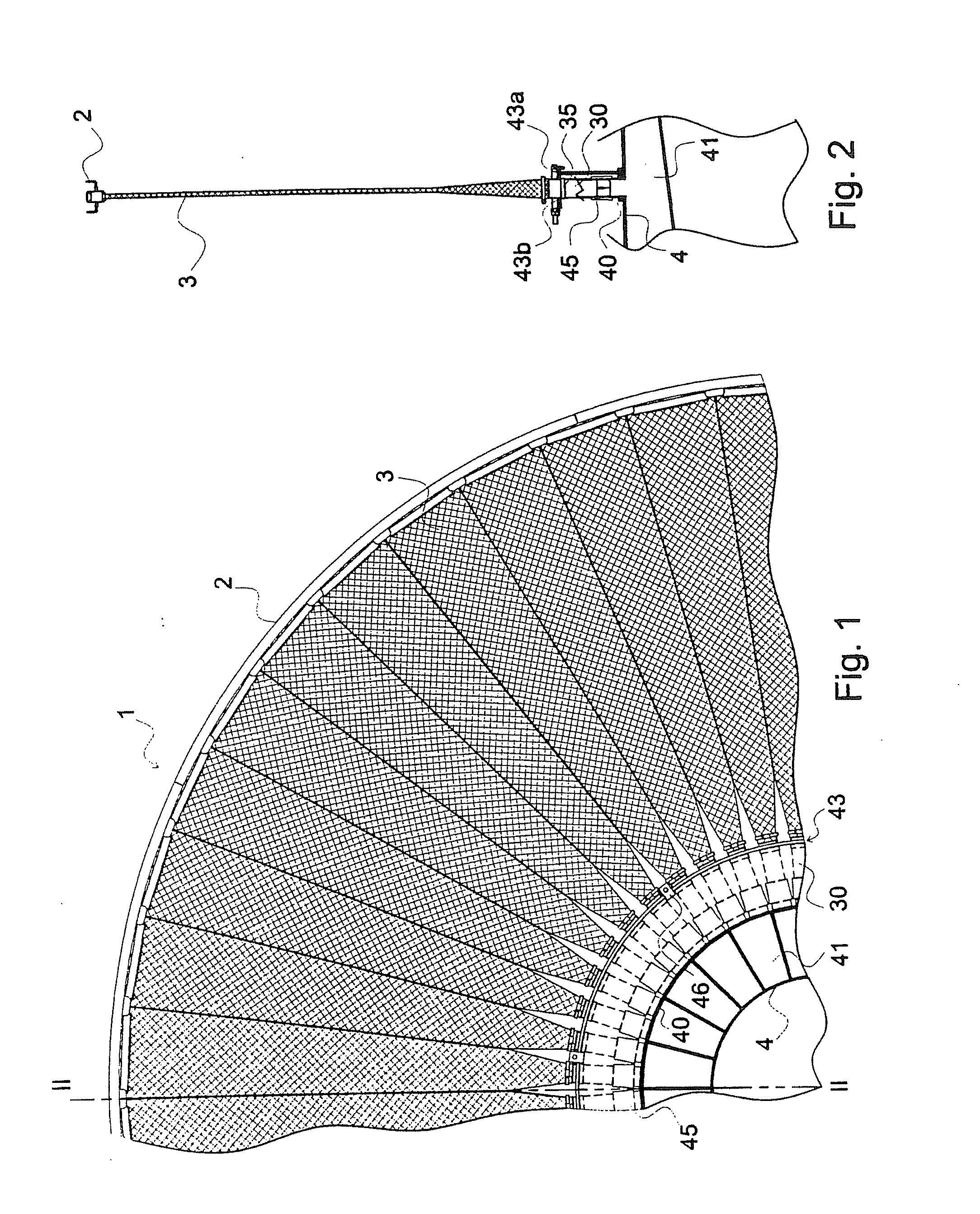
[0031]The filter device shown in FIGS. 1 and 2 includes a disc 1 provided with a rim 2 holding a plurality of filtering sectors 3. The sectors 3 are each composed of a triangular frame 31 made of a U-shaped section inserting a structure 32 in charge of draining the filtrates towards the outlet 30 provided with a tip 33, as shown more particularly in FIGS. 4A to 4C, 7A and 7B.
[0032]The sectors 3 are introduced into and accommodated in a triangular pocket 34 made from a filtering cloth opened at the base of the triangle. This pocket is further closed by folding the cloth on either side of the external edge of the sector and by wedging the cloth using a cloth clip 8 in the corner using the structure 32 supporting the cloth and the U-shaped frame 31 of the sector 3 which covers same as shown in FIG. 7B. The cloth clip 8 is made with a U-shaped section the sides of which form a jaw 82, such jaw extends almost up to the frame 31 of the sector so that it will be folded on the structure onl...
PUM
| Property | Measurement | Unit |
|---|---|---|
| Fraction | aaaaa | aaaaa |
| Time | aaaaa | aaaaa |
| Thickness | aaaaa | aaaaa |
Abstract
Description
Claims
Application Information
 - R&D
- Intellectual Property
- Life Sciences
- Materials
- Tech Scout
- Unparalleled Data Quality
- Higher Quality Content
- 60% Fewer Hallucinations
Browse by: Latest US Patents, China's latest patents, Technical Efficacy Thesaurus, Application Domain, Technology Topic, Popular Technical Reports.
© 2025 PatSnap. All rights reserved.Legal|Privacy policy|Modern Slavery Act Transparency Statement|Sitemap|About US| Contact US: help@patsnap.com


